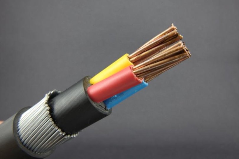
Basic electrical characteristics of wires and cables
The main electrical characteristics of wires and cables include characteristics measured at constant voltage, namely:
-
ohmic resistance of current-carrying wires,
-
insulation resistance,
-
capacity.
Ohmic resistance
The ohmic resistance of the conducting conductors of wires and cables is expressed in ohms and usually refers to a unit of length (m or km) of a wire or cable. Ohmic resistance, referring to a unit of length and cross-section, is called resistance and is expressed in ohm·cm.
In the technical conditions for wires and cables, the resistance is expressed in ohms, referring to a unit length of 1 m and a cross-section of a wire of 1 mm2.
The resistance of copper conductors of wires and cables is calculated based on the value of the resistance of copper in the products. For untempered wire (class MT) with a diameter of up to 0.99 mm — 0.0182, with a diameter over 1 mm — 0.018 — 0.0179, for heated wire (class MM) of all diameters — 0.01754 ohms mm2/m.
The specific ohmic resistance of the aluminum wire must not exceed 0.0295 ohm·mm2/ m at 20 ° C of all brands and diameters.
Insulation resistance
Insulation resistance is one of the most common characteristics of wires and cables. In the early period of cable technology development insulation resistance is considered a defining characteristic in terms of breaking strength and reliability of cable products.
At that time, insulating material was considered a very poor conductor, and obviously from this point of view it was believed that the greater the resistance of the insulation, the more that material differs from the conductor, therefore, the better it will insulate a conductor.
Standards for the insulation resistance of wires and cables are still fundamental in a number of cases, for example for wires connected to measuring instruments or circuits with low leakage current. Obviously, in this case, it is necessary to require a high insulation resistance in the same way as for all wires and communication cables, etc.
For power cables transmitting a relatively large amount of electrical energy, leakage as energy loss is practically irrelevant if it does not reduce the electrical strength and reliability of the cable, therefore the insulation resistance for power cables with impregnated paper insulation is not as important as for other types of cables and wires that transmit a relatively small amount of electrical energy.
Based on these considerations, for power cables with impregnated paper insulation, only the lower limit of the insulation resistance applicable to a length of 1 km is usually specified, for example, not less than 50 megohms for cables for voltages of 1 and 3 kV and not more than less than 100 megohms for 6 — 35 kV cables at 20 °C.
Insulation resistance is not a constant value — it strongly depends not only on the quality of the materials and the perfection of the technological process, but also on the temperature and duration of voltage application during the test.
In order to achieve greater certainty when measuring the insulation resistance, special attention should be paid to the temperature of the measured object and the duration of the voltage (electrification).
In inhomogeneous dielectrics, especially in the presence of moisture in them, a residual charge appears under the influence of a constant voltage applied to them.
To avoid obtaining incorrect results, it is necessary to carry out a long discharge of the cable before measurements by connecting the cable cores to the ground and to the lead sheath.
In order to bring the results of the measurements to a constant temperature, for example 20 ° C, the obtained values are recalculated according to the formulas, the coefficients in which are determined in advance depending on the material of the insulation layer and the construction of the cable.
The dependence of the insulation resistance on the duration of voltage application is determined by the change of the current passing through the insulation layer with a constant voltage applied to the dielectric. As the duration of voltage application (electrification) increases, the current decreases.
The greatest role is played by the insulation resistance in communication cables, because there it determines the quality of signal transmission on the cable and is one of the main characteristics. For basic cables of this type, the insulation resistance is from 1000 to 5000 MΩ and decreases to 100 MΩ.
Capacity
Capacitance is also one of the main characteristics of cables and wires, especially those used for communication and signaling.
The value of the capacitance is determined by the quality of the material of the insulation layer and the geometric dimensions of the cable. In communication cables, where lower capacitance values are sought, the cable capacitance is also determined by the volume of air in the cable (air paper insulation).
Capacitance measurement is currently used to control the completeness of cable impregnation and its geometric dimensions. In high-voltage three-wire cables, the cable capacitance is defined as a combination of partial capacitances.
To calculate the charging current of the cable when a high AC voltage is applied to it and to calculate the short-circuit currents, it is necessary to know the value of the capacitance of the cable.
Capacitance measurement is carried out in most cases with alternating voltage, and only to simplify and speed up measurements, the determination of capacitance at direct current is used.
When measuring DC capacitance, it should be borne in mind that the capacitance of the cable, determined by the ballistic galvanometer from the discharge after charging the cable with DC voltage for some time, will depend on the duration of the charge on the cable.Usually, when measuring the capacitance of wires and cables, the duration of the voltage supply is assumed to be 0.5 or 1 min.
List of characteristics of wires and cables that are measured under alternating voltage
At alternating voltage, the following characteristics of wires and cables are measured:
-
the angle of dielectric losses or rather the tangent of this angle and the increase in the angle of loss in the range of 30% from the nominal working voltage of the cable to the voltage during measurement;
-
dependence of the angle of the dielectric losses on the voltage (ionization curve);
-
dependence of the dielectric loss angle on temperature (temperature course);
-
electrical strength;
-
the dependence of dielectric strength on the duration of voltage application.
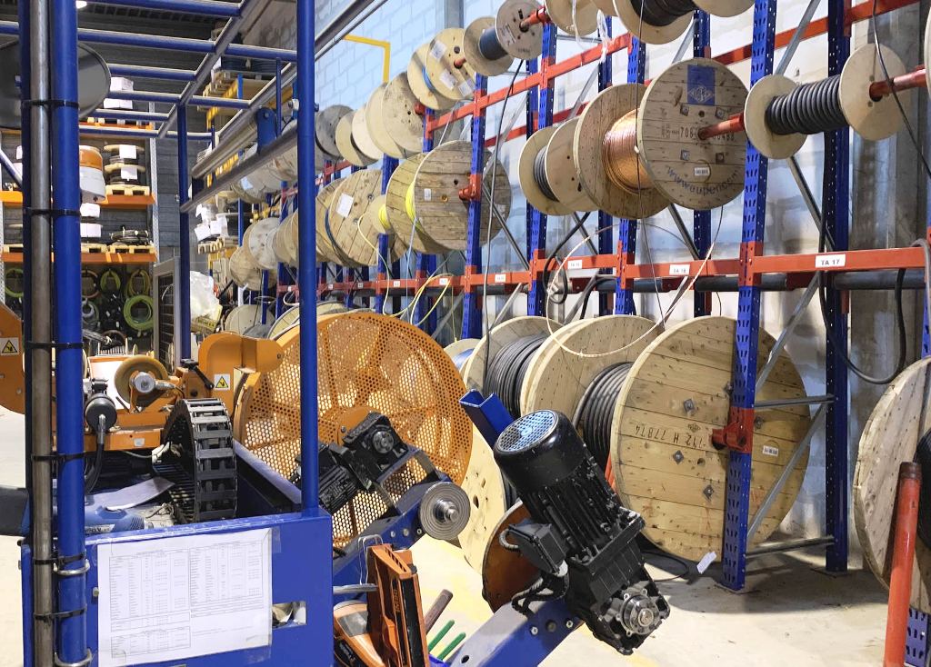
In accordance with the requirements of the technical specifications, some of these characteristics are measured on all cable reels produced by the factory (current tests), others only on small samples or lengths taken from a batch of cable reels according to a certain speed (type tests) .
Current testing of high-voltage power cables includes: measurement of the dielectric loss angle and its variation with voltage (ionization curve and increase in loss angle).
Type tests include temperature behavior and the dependence of the breaking strength of the cable on the duration of the voltage application. The impulse strength test of cable insulation has also become widespread.