How automatic transfer switching devices (ATS) work in electrical networks
In an article describing the work automatic closing devices, the cases of interruption of the power supply due to various reasons and methods of its restoration through the automatic transmission of power lines in the event that the causes of emergency situations have disappeared and ceased to operate are considered.
A bird flying between the wires of an overhead power line can create a short circuit through its wings. This will cause the voltage to be removed from the overhead line by tripping the power substation power switch protection.
After a few seconds, the automatic reclosing devices will restore the electricity supply to consumers, and the protection at this time will no longer turn it off, because the bird struck by the current will have time to fall to the ground.
However, if a nearby tree falls on the overhead power line from a gust of hurricane wind, breaks the support, then a long short circuit will occur, the wires will break, which will exclude the rapid automatic restoration of power to the connected objects.
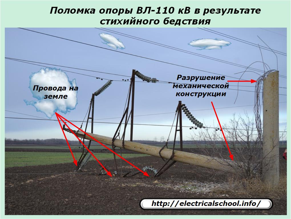
All users of this line will not be able to receive power until the repair work is completed, which could take several days...
Imagine that such damage occurs on a line that supplies electricity to a regional city with large production facilities, such as the use of automatic electric furnaces for melting glass.
In the event of a power failure, the melting baths will stop working and all liquid glass will solidify. As a result, the enterprise will suffer huge material losses, will be faced with the need to stop production, carry out expensive repairs...
To avoid such situations in all large production facilities, a backup power source is provided, consisting of a backup power line from another substation or its own powerful generator set.
You will need to quickly and reliably switch to power from it. Automatic transfer switches, abbreviated as ATS, are used for this purpose.
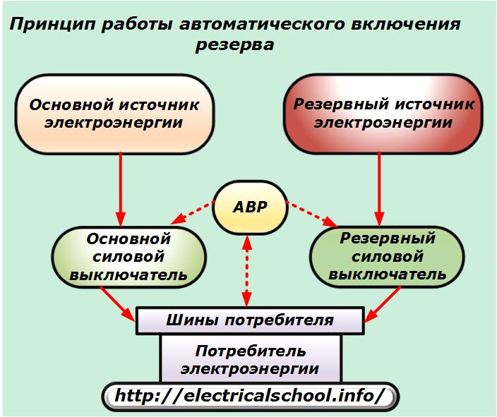
Thus, the considered automation is designed to continuously supply responsible consumers with electricity in the event of serious failures of the main power line due to the rapid activation of the backup source.
ATS requirements
Devices for automatically introducing backup power must be activated:
-
as soon as possible after a loss of electricity on the main line;
-
in case of loss of voltage on the user's own buses, without analyzing the causes of the malfunction, if the blocking of the start by a certain type of protection is not provided. For example, the arc protection of the tires must block the start of the automatic transfer switch to prevent the development of the resulting accident;
-
with the necessary delay when performing certain technological cycles. For example, when switching on under the load of powerful electric motors, a "voltage drop" is possible, which ends quickly;
-
always only once, because otherwise it is possible to turn on several times for an irreparable short circuit, which can completely destroy a balanced electrical system.
A natural requirement for the reliable operation of the circuit is its constant maintenance in good condition and automatic control of technical parameters.
Advantages of ATS over parallel supply from two sources
At first glance, in order to power responsible consumers, you can completely cope with simultaneously connecting them to two different lines that take energy from different generators. Then, in the event of an accident on one of the overhead lines, this circuit will break, and the other will remain operational and provide continuous power.
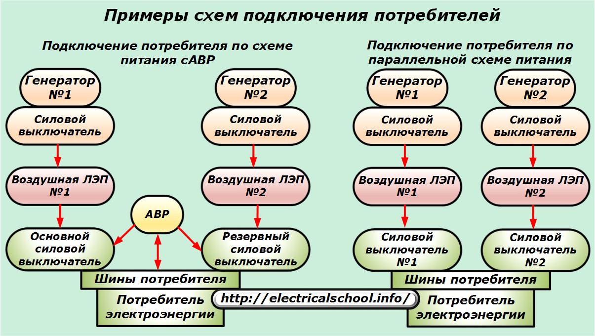
Such schemes have already been created, but have not received mass practical application due to the following disadvantages:
-
in the event of a short circuit on either line, the currents increase significantly due to the supply of energy from both generators;
-
power losses in power transformer substations are increasing;
-
the power management scheme becomes much more complex due to the use of algorithms that simultaneously take into account the state of the user and two generators, the occurrence of energy flows;
-
the complexity of implementing the protections interconnected by algorithms at the three remote ends.
Therefore, powering the user from one main source and automatic transfer to the backup generator in the event of a power failure is considered the most promising. Power outage time with this method can be less than 1 second.
Features of creating ATS schemes
One of the following algorithms can be used to control the automation:
-
unidirectional power supply from a workplace with an additional hot standby mode, which is put into operation only on loss of voltage from the main source;
-
the possibility of bilateral use of each of the sources as a workstation;
-
the ability of the ATS circuit to automatically return to power from the primary source after voltage is restored to the input switch buses. In this case, a sequence of actuation of power switching devices is created, excluding the possibility of connecting the user to the mode of parallel power from two sources;
-
a simple ATS scheme that excludes the transition to the power recovery mode from the main source in automatic mode;
-
the backup power supply should only be introduced if arrangements have been made to supply voltage to the failed main power supply element by turning off the relevant switch.
Unlike automatic reclosing, automatic reclosing, ATS devices show the highest efficiency in the event of a power failure, calculated at 90 ÷ 95%. Therefore, they are widely used in power supply systems of industrial enterprises.
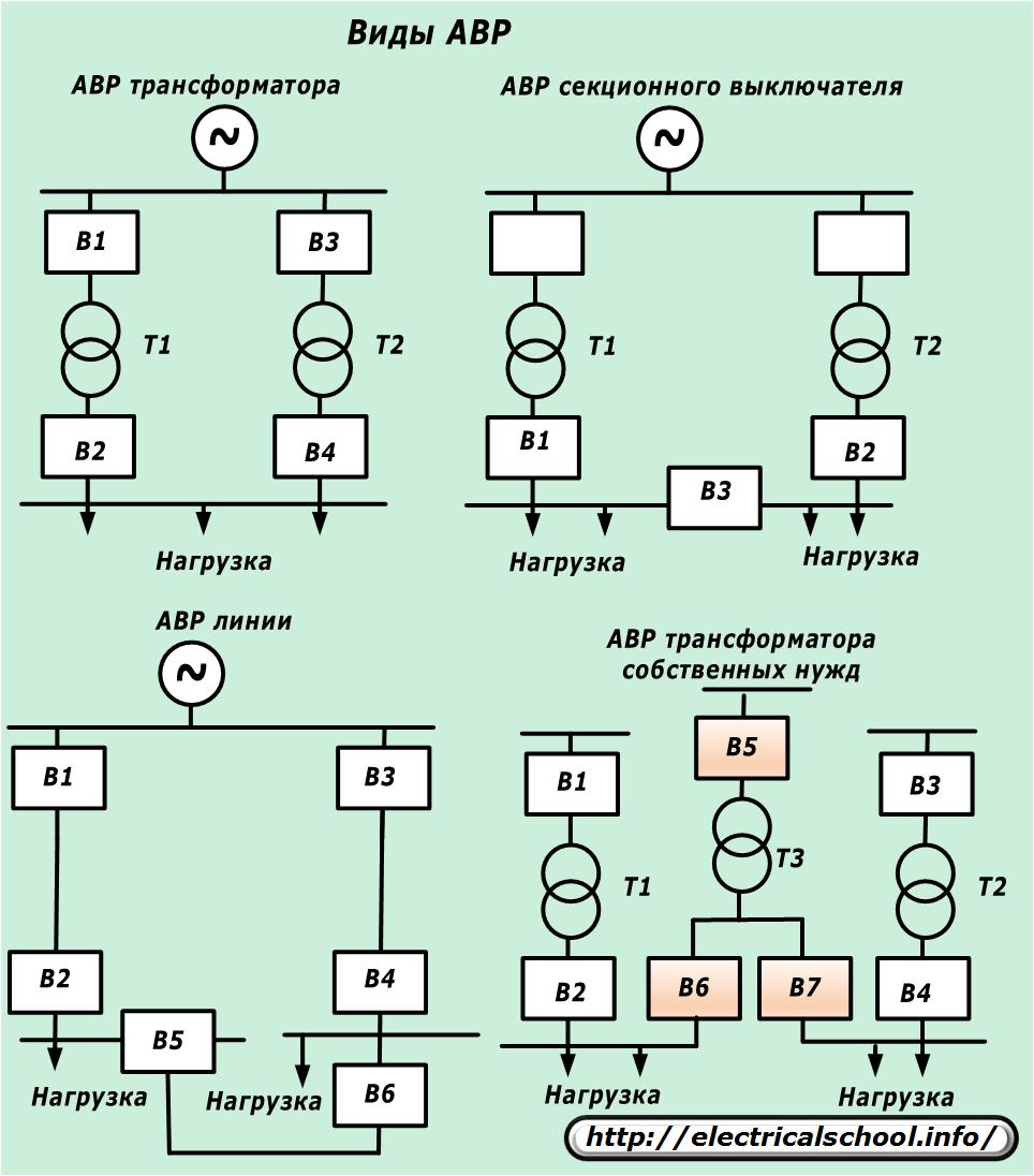
Automatic switching on of the reserve is used to power power lines, transformers (power supply and auxiliary needs), sectional switches.
The principles underlying the work of OVD
To analyze the voltage of the main power line, a measuring device is used, which consists of a voltage control relay RKN in combination with a measuring transformer and its circuits. The high-voltage voltage of the primary network, proportionally converted to a secondary value of 0 ÷ 100 volts, is fed to the coil of the control relay, which acts as a trigger.
The setting of the RKN relay settings has a peculiarity: it is necessary to take into account the low required level of actuation of the actuating element, which guarantees the voltage drop to 20 ÷ 25% of the nominal value.
This is due to the fact that in the case of close short circuits, a short-term "voltage drop" occurs, which is eliminated by the operation of overcurrent protections. And ILV startup items must be restored by these processes. However, it is impossible to use conventional types of relays because of their unstable operation at the initial scale limit.
For operation in the starting elements of ATS, special relay designs are used, which exclude vibration and bounce of contacts when actuated at lower limits.
When the equipment is normally powered according to the main circuit, the voltage monitoring relay simply observes this mode. As soon as the voltage disappears, the RKN switches its contacts and thus signals the solenoid to turn on the solenoid of the backup switch to actuate it.
At the same time, a certain sequence of activation of the power elements of the first loop is observed, which is included in the control logic of the ATS system during its creation and configuration.
In addition to the loss of voltage on the main power line, for the full operation of the starting element of the ATS, it is usually necessary to check a few more conditions, for example:
-
absence of unauthorized short circuit in the protected area;
-
turn on input switch;
-
the presence of voltage on the backup power line and some others.
All initial factors entered for the operation of the ATS are checked in the logic algorithm and, if the necessary conditions are met, a command is issued to the executive body, taking into account the set time setting.
Examples of application of some ATS schemes
Depending on the magnitude of the operating voltage of the system and the complexity of the network configuration, the ATS circuit can have a different structure, run on direct or alternating current, or do without it at all, using the main network voltage in 0.4 kV circuits.
ATS on a high voltage line at constant operating current
Let's briefly look at the logic of operation of the backup power relay circuit with the main power supply #1.
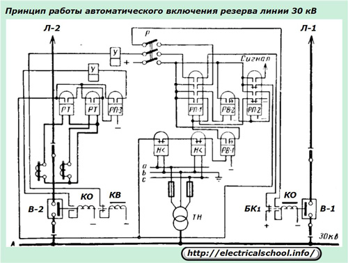
If a short circuit occurs in the L-1 section, then the protections will turn off the switch V-1 and the voltage on the connecting buses will disappear. The undervoltage relay «H <» will sense this through the measuring VT and operate by supplying + operating current through the RV contact, which has operated with a time delay, to the RP coil.
Its contacts will trigger commands to actuate a number of relays that perform various monitoring functions and provide a control signal to the V-2 power switch closing solenoid.
The scheme provides single action and release of actuation information from signal relays.
ATS of a sectional switch at constant operating current
The operating power transformers T1 and T2 supply their section of busbars disconnected from section switch V-5.
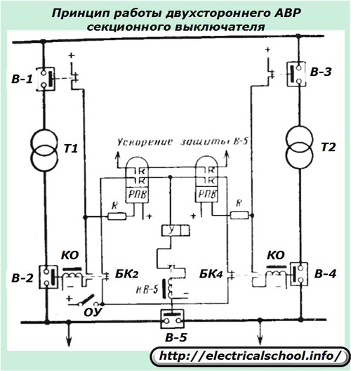
When one of these transformers is tripped or interrupted, power is applied to the tripped section by switching the V-5 switch. The RPV relay provides one-time automatic closing.
The operation of the circuit is based on the interaction of the auxiliary contacts of the switch with the supply of + operating current to the coils of the RPV relay and the turn signals. It also provides for the operational acceleration of the operating system, which is put into operation during the switches by the personnel on duty.
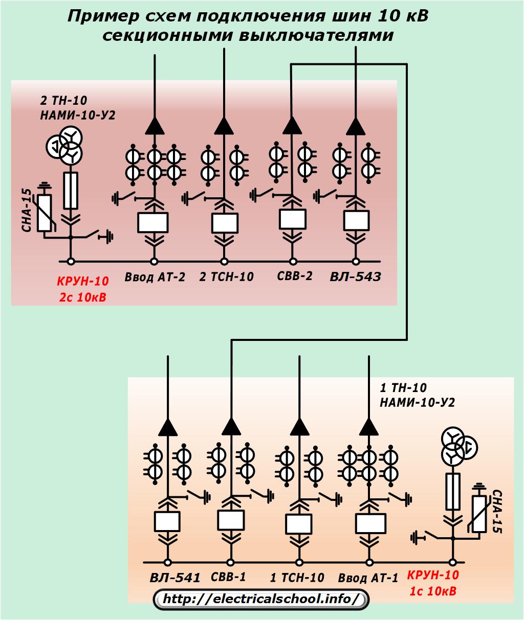
The principle of formation of the logic of operation of ATS can be changed. For example, when operating a circuit with an additional section switch included, as shown in the photo below, additional starters and logic elements will be required.
ATS sectional switch in alternating current operation
Features of the operation of the automation of sources that use energy from those located in the substation VT measurement, can be estimated according to the following scheme.
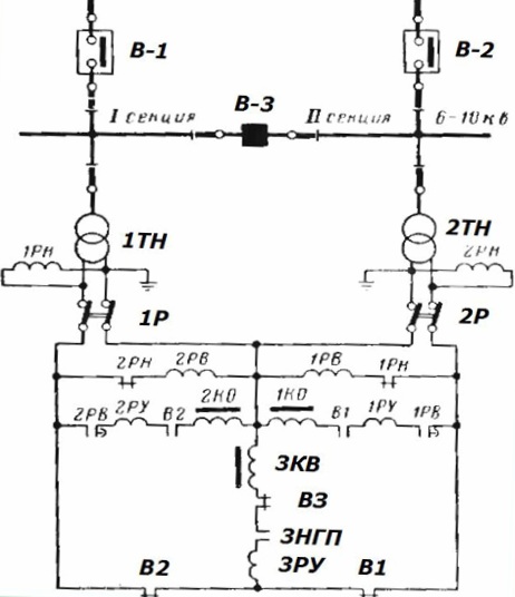
Here the voltage control of each section is done by the 1PH and 2PH relays. Their contacts actuate the 1PB or 2PB synchronizing bodies, which act through the block contacts and flashing coils of the power switch solenoids.
The principle of implementation of ATS of users of a 0.4 kV network
When creating a backup power supply for a three-phase network, magnetic starters KM1, KM2 and a kV minimum voltage relay are used, which controls the parameters of the main line L1.
The starter windings are connected from the same phases of their lines through the logic switching contacts to the grounded neutral, and the power contacts tap into the consumer's supply busbars on both sides.
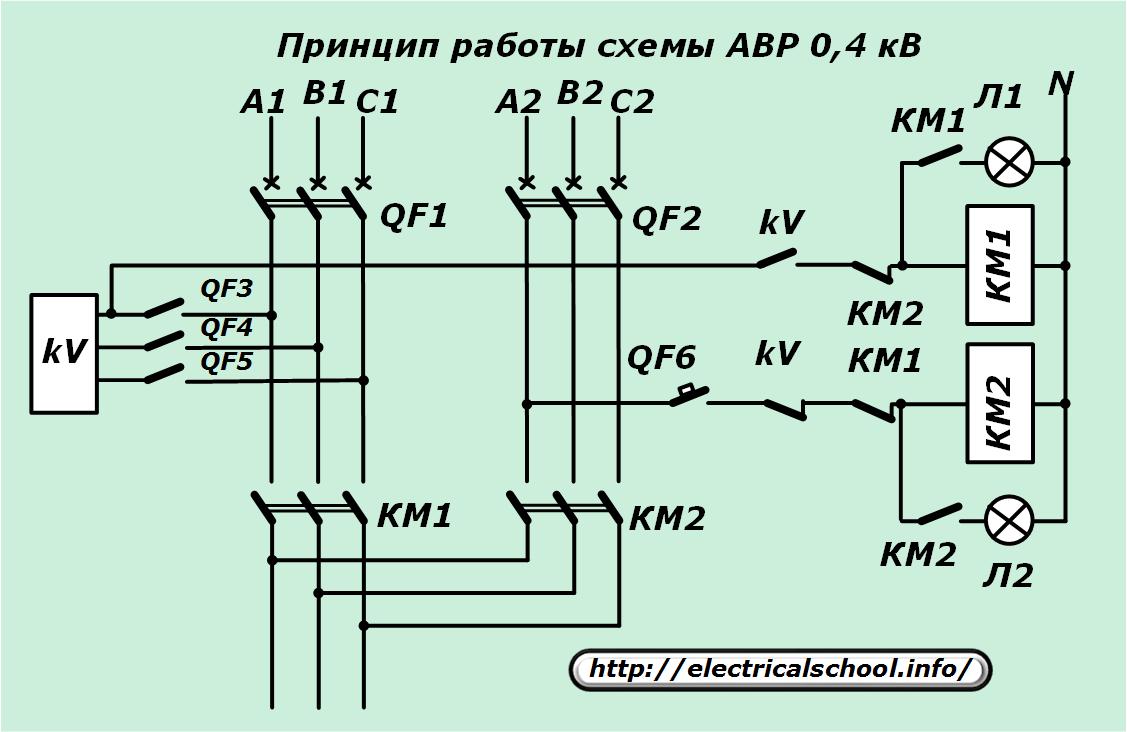
The contact system of the voltage relay in each position connects only one starter to the mains. In the presence of voltage on the L1 line, the kV will operate and with its closing contact will turn on the coil of the starter KM1, which will supply the user with its supply circuit and connect its signal light, while disabling the KM2 winding.
In the event of a voltage interruption on L1, the kV relay interrupts the supply circuit of the starter winding KM1 and starts KM2, which performs the same functions for the L2 line as KM1 for its circuit in the previous case.
Power switches QF1 and QF2 are used to completely de-energize the circuit.
The same algorithm can be taken as the basis for creating a power supply for responsible users in a single-phase power network.You just need to turn off the unnecessary elements in it and use single-phase starters.
Features of modern ATS sets
To explain the principles of building automation algorithms, the old relay base has been deliberately used, which makes it easier to understand the algorithms at work.
Modern static and microprocessor devices work on the same circuits, but have improved appearance, smaller sizes and have more convenient settings and capabilities.
They are created in separate blocks or in whole sets assembled in special modules.

For industrial use, ATS kits are manufactured as fully ready-to-use kits housed in special protective enclosures.