Small hydroelectric plants - types and projects
Hydroelectric plants are a set of components that are interconnected and serve to convert energy (kinetic and potential) into electrical energy or vice versa.
According to the existing classification, the small ones are hydroelectric power plants (HPP) power up to 10-15 MW, including:
-
small hydropower plants — from 1 to 10 MW.
-
mini-hydroelectric plants — from 0.1 to 1 MW.
-
micro-hydroelectric plant — with a capacity of up to 0.1 MW.
Flow and head play a decisive role in the capacity of a hydroelectric plant. Flow and pressure are regulated using a water supply pre-accumulated in the upper part of the water. The more water in the tank, the higher the pressure water level and, accordingly, the head.
The source of hydropower potential used in hydropower is large medium and small rivers, irrigation and water supply systems, slope runoff of glaciers and permanent snow.HPPs mainly differ from each other in the way they create pressure, the degree of flow regulation, the type of installed main equipment, the complexity of using the water flow (single or multi-functional), etc.
Small hydropower plants (small hydroelectric plants) play a particularly important role in supplying electricity to autonomous consumers scattered far from power lines. The article discusses common projects that use the energy of small streams.
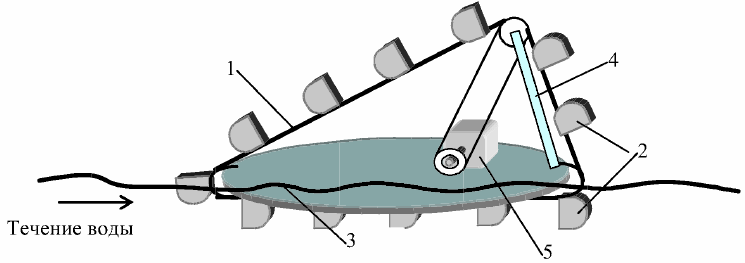
The setup for using the current environment is shown in Fig. 1 a. It functions as follows. When the vertical vanes 1 are influenced by the flowing medium, a hydrodynamic force occurs that drives the ballast rims. Through the kinematic link 3, the support transmits torque to the generator shaft, while the generator itself remains stationary. This hydroelectric plant operates on lowland watercourses whose size and energy determine its capacity.
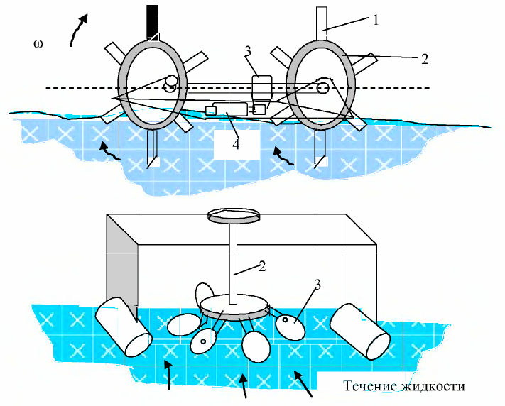
Rice. 1. Schemes of operation of a flat hydroelectric plant: a) flat hydroelectric plant, b) b) hydroelectric plant.
The hydroelectric plant (Fig. 1, b), while moving, uses the energy of the liquid by means of the impeller 6. The impeller 1 contains a shaft and vanes located on it. The installation is mounted on a frame 7 fixed on pontoons 6. The blades, perpendicularly inclined to the direction of the water flow, change their orientation to the flow with the help of the wheel 4.
One of the blades is made of a composite of interlocking inner and outer parts, having a transverse connector located at an angle to the axis, and is weakened by an elastic pad placed between the parts and an elastic connection.The elastic connection is made in the form of a package of plates facing the flow of the medium, of variable length, adhering to the blade and in contact with its outer part. The device is oriented to a flat water flow. Applied power generating machines can be of synchronous and asynchronous type.
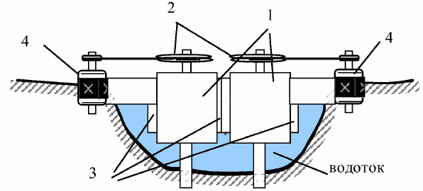
In the shown in fig. 2, the fluid flow from control valve 1 is alternately diverted into chambers 2 and 3 and vice versa.
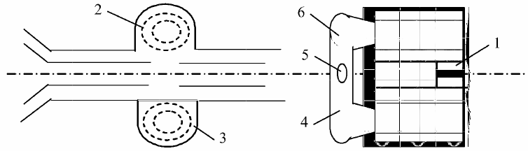
Rice. 2. Turbine in the flow path of the siphon
The rotational movement of the liquid in the chambers causes air oscillations and their overflow through pipelines 4 and 6 with the activation of the turbine 5 and the generator connected to it. To improve the efficiency of the entire device, it is installed in the flow path of the siphon. The prerequisites for problem-free operation are flowing liquid, clean without large fractions. A trash rack is required for this installation.
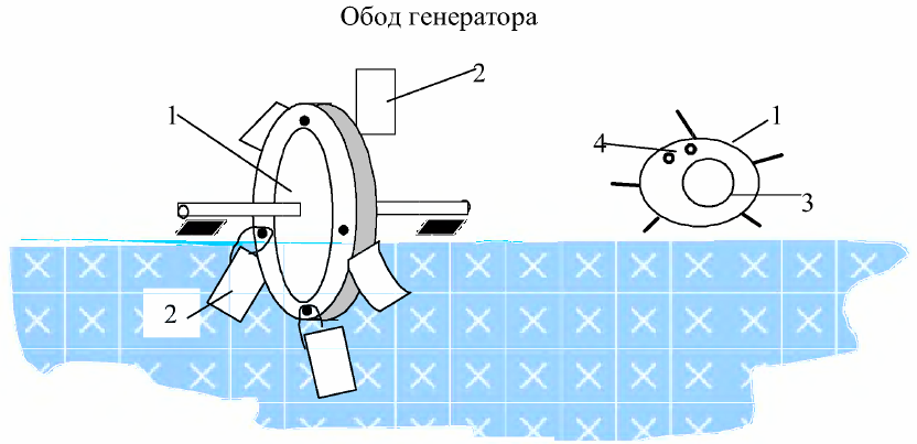
A floating water turbine with a power of 16 kW (Fig. 3) is designed to convert the kinetic energy of the flow into mechanical and then into electrical energy. The turbine is an elongated circular element made of light (lighter than water) material with helical fins on the surface. The element is suspended on both sides by rods that transmit torque to the generator.
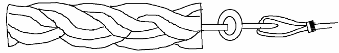
Fig. 3. Floating water turbine
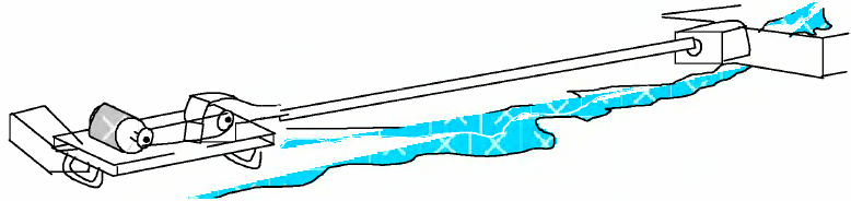
The hydraulic power plant (Fig. 4) is designed to generate electricity through a mini-generator, which is driven in rotation by an endless drive belt 1 with water buckets 2 located on it. A belt 1 with buckets 2 is mounted on a frame 3 capable of being carried on waves . Frame 3 is attached to a support 4 on which the generator 5 is located.
The buckets are located on the outside of the belt with the open sides facing the horizontal direction of the water flow.The number of buckets is determined by the condition for ensuring the rotation of the generator. A variant of using a "ladder" type device with attached blades is possible.
Rice. 4. Assembly of belt and bucket
The device for using the kinetic energy of the flows consists of vertical cylinders located in the water on opposite banks, on which a roller is placed (Fig. 5).
Rice. 5. Installation of a micro dam
The blades are mounted between the upper and lower axis of the roller. Due to the angle of attack between the vanes and the velocity vector, the flowing water drives the cylinders in rotation, and through the roller, a generator that generates electricity.
The device for using the energy of the flows consists of an impeller 1 located vertically in the water flow, with hinged vanes 2 on the upper 1 and lower 3 rims (Fig. 6). The upper edge 1 is connected to the generator 4. The position of the vanes 2 is regulated by the flow itself: perpendicular to the front flow and parallel to the upstream movement.
Rice. 6. A device that converts the energy of water flow
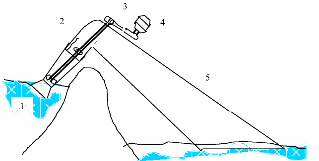
The sleeve micro-hydroelectric power plant 1 kW (MHES-1) consists of a turbine in the form of a squirrel wheel 1, a guide vane 2, a flexible pipeline 3 with a diameter of 150 mm, a water suction device 4 , a generator 5, a control unit 6 and frame 7 (Fig. 7).
Rice. 7. Bushing micro hydropower 1 kW
The operation of this MicroHPP is carried out as follows: the water intake device 4 concentrates the hydraulic medium and through the pipeline 3 provides a height difference between the upper water level and the working turbine 1, the interaction of a certain pressure of the hydraulic fluid with the turbine drives the latter in rotation.The torque of the turbine 1 is transmitted to the electric generator.
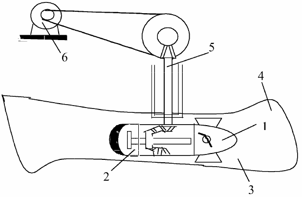
A siphon hydroelectric plant (Fig. 8) is used where there is a drop of hydraulic fluid at a height of 1.75 m from the dam or as a result of natural conditions.
Rice. 8. Siphon hydraulic unit
The operation of these installations is as follows: the passage of hydraulic fluid through the turbine 1 rises through the crest of the dam, fig. 9, the torque is transmitted through the shaft 2 and the belt gear 3 to the electric generator 4. The spent liquid medium enters the back water through the expanding water line.
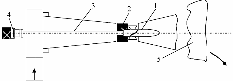
A low-pressure micro-hydroelectric installation (Fig. 9) operates with a nominal head of the liquid column of at least H = 1.5 m. As droop decreases, output power decreases. The recommended drop height is 1.4-1.6 m.
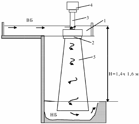
Rice. 9. Low pressure hydroelectric plant
The principle of operation is based on the interaction of hydraulic fluid with potential energy, converted into rotary and then into electrical form. In the suction device 1, the liquid enters the turbine 2, the liquid is pre-vortexed and, further penetrating the branch pipe due to the falling liquid, interacts with the blades of the turbine 2, converts the kinetic energy of the liquid into a torque on the shaft 3, then to the electric generator.
The weight of the low-pressure station is 16 kg with power P = 200 W. The propeller semi-direct hydropower converter consists of a pressure pipeline 1, a guide grid 2, a propeller turbine 3, a rounded outlet channel 4, a torque transmission shaft 5 and electric generator 6 (fig. 10).
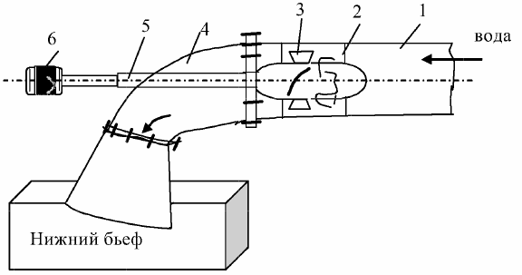
Rice. 10. Semi-direct flow converter
The electrical power of this design is in the range 1-10 kW with a difference in height Nm = 2.2-5.7 m. Water consumption QH = 0.05-0.21 m 3m / s. The difference in height Nm = 2.2-5.7 m. The speed of rotation of the turbine will be wn = 1000 rpm.
The capsule hydraulic converter based on the 2PEDV-22-219 electric motor (Fig. 11) works similarly to the previous hydroelectric power plant with a head H = 2.5-6.3 m and a water flow rate Q = 0.005-0.14 m 3 / s Electric power 1-5 kW. The diameter of the water turbines is from 0.2 to 0.254 m. The diameter of the hydraulic wheel is Dk = 0.35-0.4 m.
Rice. 11. Capsule micro-hydroelectric plant
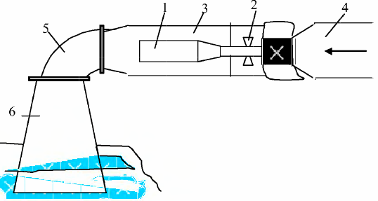
The direct flow hydraulic converter (Fig. 12) consists of a propeller turbine 1, a guide grid 2, a torque transmission shaft 3, an electric generator 4, an exhaust pipeline 5. It works using a pressure pipeline.
Rice. 12. Direct flow hydraulic converter
The hydroconverter (Fig. 13) is designed to convert the energy of a fast-moving liquid medium into electrical energy.
Rice. 13. Hydraulic energy converter for fast water flow
It consists of a propeller turbine 1, located in a capsule 2, and is installed on water currents called «quick currents». The capsule is located in the guide vane 4, which is mounted inside the fluid medium. The torque from the turbine is transmitted to the shaft 5, and then to the electric generator 6.