Operating and electrical protective characteristics of earthing devices
 The main operating function of earthing devices is to provide sufficient conductivity for the operation of the relay protection circuit to close the live parts of the electrical installation to the grounded frame or ground.
Therefore, the most important electrical characteristic of the grounding device is grounding conductivity Gzy or its inverse value Rz — resistance of the grounding device equal to Rzy = Rs + Rzp, where Rz is the resistance of the current that spreads from the grounding electrode to the ground (resistance of grounded electrode), RZn — resistance of the grounding wires.
The resistance of a current that propagates from the grounding electrode into the ground is formed by the entire current propagation zone — the volume of the ground, starting from the surface of the grounded electrode, the electric potential φ which during the passage of current Азs in the ground is φ3, and to the zone where φ is practically zero (zone of zero potential).
In accordance with Ohm's Law grounding resistance is equal to the ratio of the potential of the nodes at the point of current introduction to the grounding electrode to the current Azz leaving the grounding electrode in the ground Rs = φsmax /Азс
Note that the potential φ wave numerically equal to the voltage of the grounding electrode Uz. Therefore, the formula is usually written in the form Rs = Uc /Azc
The electrical protective function of the earthing device consists in limiting the voltage to the permissible limits at which a person can come into contact with the grounded body of the electrical installation (with the metal structural parts of the electrical installation that are not normally energized) during the closing of the phase to the enclosure or ground.
Consider a case short circuit in an electrical network above 1 kV with an effectively grounded neutral (with high ground fault currents, Fig. 1). The electrical circuit includes the phase of the supply transformer, the conductor of the supply wire, the body of the supplied transformer, its earthing device, the earth, the earthing device of the supply transformer.
A distribution of the potential φ on the earth surface in the current spreading zone corresponds to the generally accepted positive direction for the current Azz entering the earth from the earthing device of the supply transformer. The earth potential has the largest positive value φmax at a point located above one of the central electrodes of the grounding electrode.
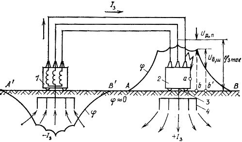
Rice. 1.Electrical diagram of a short circuit to the housing in a network with a voltage higher than 1 kV with effective neutral grounding: 1 — power transformer; 2 — electric receiver; 3 — grounding wire; 4 — ground electrode; A — B and A ' — B' — current dispersal zones; a, b — points of possible simultaneous contact of the person with the grounded housing and the ground; b, b'- points in the current spreading zone, on which a person can simultaneously step
With the distance from the grounding electrode, the potential in the ground decreases relatively quickly, and at a distance approximately equal to 20 large diagonals of the contour of the grounding device, it becomes less than 2% of the grounding potential φmax. At such a distance from the grounding electrode, the potential is usually considered zero.
Similarly, the potential changes near the earthing device of the supply transformer. In relation to the assumed direction of the current, its potential is considered negative.
There are two main dangerous situations in which a person in the area of current distribution can become energized. The first situation — a person stands on the ground in transformer substations, switchboards and other devices and touches the metal grounded parts of the electrical installation.
In fact, the absolute values of the potentials of the points on the earth's surface in the current spreading zone, including φmax, is always less than that of the grounded metal parts of the electrical installation, whose potential, if we ignore the voltage drop in the horizontal electrodes of a complex grounding system , is a φ wave.
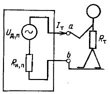
Therefore, when a person stands in the area of current distribution, for example at point b (Fig.1) and does not touch the grounded body of the electrical installation, then between the body (point a in Fig. 1) and point b the so-called touch voltageUdp, which can be considered as the open circuit voltage of an active two-terminal network with a known internal resistance (Fig. 2), numerically equal to the resistance of a current spreading from two human feet into the ground Rnp.
Rice. 2. By definition Un: a and b — points according to figure 1 that a person touches with a hand (palm) and foot (sole)
If a person is standing at point b"Touching point a, then he falls under a touch voltage Up, equal to the product of the current according to Ohm's law Azt passes, but his body, on the resistance of his body RT: Un = Azt x RT.
Current Azm is equal to the ratio Udp to the sum of the resistances Rt and Rnp: Azt = Udp /(Rt +Rnp), Upp = (UdpNS RT)/(Rt + Rnp)
Meaning RT/(Rt + Rnp) is usually denoted by the letter βp... Then Upp = Udp x βp. notice that βp is always less than one and therefore Up is less than Udp.
The second dangerous situation is related to the fact that in the area of current propagation, a person usually stands or walks so that his feet are at points with different potentials, for example, at points b and b' in fig. 1. To characterize the second dangerous situation, we introduce the concepts of step voltages and step voltages.
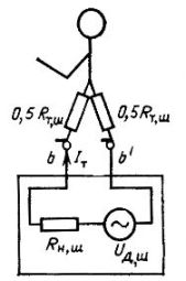
Rice. 3. According to UNC definition: b, b'- points according to fig. 1., on which the person stands.
Step voltage Udsh is the potential difference between two points on the ground in the area of current distribution, on which a person can simultaneously step.
By analogy with the first dangerous situation, the Udsh value can be interpreted as the open circuit voltage of an active two-terminal network with a known internal resistance (Fig. 3). When a person steps on the points between which Udsh acted, the resistance of the human body Rtsh along the path "foot - foot" is included in the bipolar circuit.
In this case, the internal resistance of an active two-terminal network is the step current dissipation resistance Rtsh, which can be simplified as the sum of two identical resistances to the current spreading to the ground from each human leg.
The step voltage is defined as follows: Uw = Azt x Rtsh.
The concepts of touch and step stress also apply to animals. In this case, the touch voltage is understood as the potential difference between the nose mirror or the neck and the legs, and the foot voltage is between the front and rear legs.
The main characteristics by which it is possible to establish the operational and electrical protective qualities of the grounding devices are the resistance of the grounding electrode (Rz), the touch voltage (Up) and the step voltage (Ush) found during the calculated season at the calculated value of the current Azz.
The values of Up and Ush depend on the coefficients of the character of the current field leaving the person's feet in the ground, and the resistance of the person's body, which is a function of the current passing through his body, and the resistance Rz . Therefore, in order to calculate the resistance of the grounding device and touch and step voltages, it is necessary to be able to calculate the electric fields of currents leaving the ground electrodes in the ground.