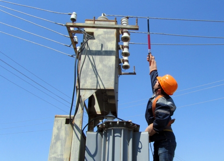
Induced voltage and measures to protect against it
Voltage is induced on overhead power lines by lines operating in the neighborhood, this voltage is not directly related to the voltage of the line itself and is therefore called induced.
In connection with this fact, the safety rules for the operation of electrical installations determine the protective measures that must be taken to ensure safety when working on overhead lines. Safety measures are also noted as a separate item in conditions where grounding does not help to reduce the value of the induced potential of the disconnected wires below 25 volts.
Meanwhile, service personnel occasionally experience electric shock due to induced voltage. This happens due to a lack of understanding of the true nature of induced voltage, how it occurs, what the mechanism is. The danger persists in one way or another, because even touching a properly grounded conductor that is susceptible to voltage induction from an adjacent line can electrocute a person.
The conclusion is that any overhead line which runs parallel to other overhead lines is all the time experiencing the inductive action of neighboring lines from which the potential is induced upon it.
The electromagnetic fields of the lines interact with each other, while the value of the induced voltage is associated with both the operating voltage and the load current, as well as the distance between the phase conductors of the lines, in addition to the length of the section along which these conductors run in parallel is significant. A potential is induced in each of the lines, which consists of two components: electrostatic and electromagnetic interactions.
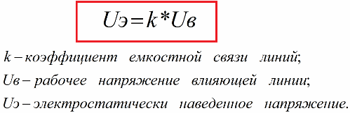
The first component is electrostatic. Induced by this component, the voltage is related to the interaction of the electric field of the influencing line on the considered disconnected. Value of induced voltage, even subject to PUE, but with parallel passage of these lines, depends on the voltage on the influencing line. The voltage induced on the disconnected overhead line turns out to be the same along its entire length and turns out to be equal to:
Induced voltage distribution diagram:
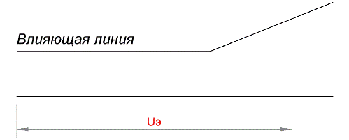
The electrostatic component of the induced voltage can be reduced to a safe value along the entire length of the line by grounding at least one place. That is, if such an overhead line is grounded at its ends, then the effect of the action of the electrostatic component will be completely eliminated. The disconnected air line, grounded at the ends, during its maintenance, in accordance with safety rules, must be grounded at the workplace.
The electromagnetic component differs in its mechanism of action from the electrostatic one. The induced voltage from the electromagnetic component is due to the action of the magnetic fields of the currents of the phase conductors belonging to the influencing line. So the EMF directed at the disconnected overhead line will be equal to:
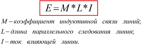
What matters here is the coefficient of inductive coupling, which is unchanged for the corridors of the considered lines, but the EMF value is determined by the length of the section along which the lines follow in parallel. The load current in the influencing line also matters, but not the line voltage. The voltage to ground at point x will be equal to:
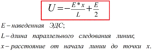
It is obvious from the formula that at the beginning of the line the voltage induced by the electromagnetic component will be + E / 2, in the middle of the line 0 and at the end -E / 2. The electromagnetic component of the induced voltage is unchanged due to the insulation of the wire from the ground or grounding it at one or more points.
As the number of grounding points on the overhead line increases, only the location of the zero potential point on the line shifts. In accordance with this characteristic of the electromagnetic component of the induced voltage, safety rules are provided.
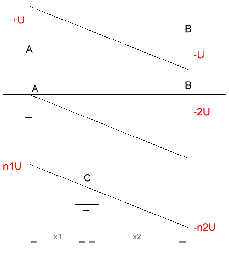
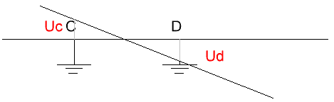
The diagrams show that the distribution of the electromagnetic component of the voltage induced on the disconnected overhead line depends on the point of the grounding position. If there is only one ground, then the zero point of the induced potential will coincide with the single ground point.
These diagrams justify the potential danger to service personnel if work is carried out simultaneously at two or more locations on the overhead line, since the overhead line grounded at one point is below the effective value of the induced electromagnetic component of the EMF. So if one of the teams works at the grounded point C, then the voltage there is zero.
The second workplace D can also be equipped with protective earthing, but then the point of zero potential will be shifted in the direction between points D and C, and the voltages at the points D and C themselves may exceed safe values, and people will already be exposed to risk.
A similar effect occurs when working on line disconnector, which is under the influence of the induced voltage from the overhead line. The disconnector must be grounded on the line side, then workers will be safe if this ground is the only one for the service line.
Otherwise, if there is another earth, for example in a substation located at the other end of the service line, then the induced voltage at the point of operation will increase to a maximum and people will be in danger. The figure shows an explanatory diagram.
The induced voltage factor forces workers to resort to working only one team per line if that overhead line is under the influence of induced voltage. Another option is to divide the line into several separate, unconnected sections and then restore them one by one, and although this solution is associated with unnecessary costs, it is resorted to in order to ensure the safety of people.The alternative is live work, after which several teams can work on one line at a time.
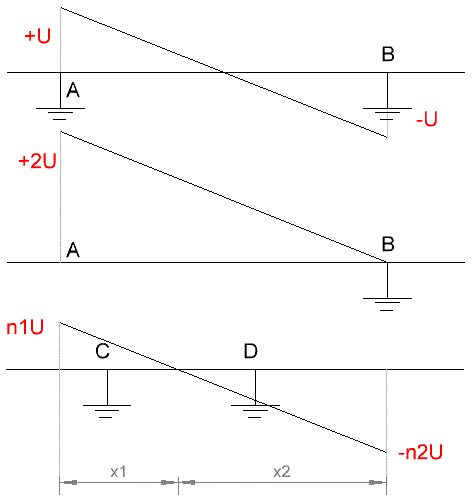
In the process of preparing a workplace for the brigade, special attention is paid to the reliability of the contact connections of phase wires with protective earthing devices.
If the contact is accidentally lost, the point of zero potential will immediately shift to another place, and the workplace will be under induced voltage and people will be at risk. For this reason, it is best to make two defenses of reliability. The figure gives an explanation of this nuance.
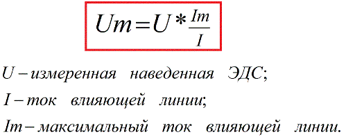
The maximum of the induced electromagnetic component of the voltage falls on the boundaries of the interaction zone of the line, in particular on the disconnected line disconnectors. At these points on the grounding bus of the line disconnector or on the first support, counting from the substation, measurements are made with earths included at both ends of the line. Accordingly, voltmeters are selected, the class of which must fit within the expected limits up to 500 - 1000 volts.
When the maximum current of the influencing line is known, after carrying out measurements in the current mode, it becomes possible to calculate the maximum induced voltage, which is calculated by the formula:
It is important to keep safety basics in mind while taking measurements. The connecting wires, the frame of the disconnector and the voltmeter itself can be energized, and for safe operation you must first assemble the measuring circuit and only then connect it to the phase wires.
Connecting wires must be insulated for a minimum voltage of 1000 volts.Workers should wear dielectric boots and gloves. If during the measurement it is necessary to change the measurement limits of the voltmeter scale, you will first need to disconnect the entire measuring circuit from the line.