Everything you need to know about grounding
Grounding. The basics
 Grounding — electrical connection of an object of conductive material to earth. Grounding consists of a ground wire (a conductive part or set of interconnected conductive parts that are in electrical contact with the ground directly or through an intermediate conductive medium) and a ground wire connecting the device to be grounded to the ground wire. The earthing switch can be a simple metal rod (most often steel, less often copper) or a complex complex of specially shaped elements.
The quality of grounding is determined by the value of the electrical resistance of the grounding circuit, which can be reduced by increasing the contact area or the conductivity of the medium — using many rods, increasing the salt content in the ground, etc. Grounding device in Russia, the requirements for grounding and its arrangement are regulated Rules for Electrical Installation (PUE).
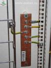
Protective grounding conductors in all electrical installations, as well as neutral protective conductors in electrical installations with a voltage of up to 1 kV with a solidly grounded neutral, including buses, must have the letter designation PE and a color designation with alternating longitudinal or transverse stripes of width (for buses from 15 to 100 mm) yellow and green.
Zero working (neutral) wires are marked with the letter N and blue. The combined zero protective and zero working conductors must have the letter designation PEN and a color designation: blue along the entire length and yellow-green stripes at the ends.
Faults in the grounding device
Wrong PE wires
Sometimes water pipes or heating pipes are used as a grounding conductor, but they cannot be used as a grounding conductor. The water line may have non-conductive inserts (e.g. plastic pipes), the electrical contact between the pipes may break due to corrosion, and finally, some of the pipes may be disassembled for repair.
Combining working neutral and PE wire
 Another common violation is the unification of the working neutral and the PE conductor behind the point of their separation (if any) on the power distribution. Such a violation can lead to the appearance of fairly significant currents along the PE wire (which should not carry current in a normal state), as well as false positives on the residual current device (if installed). Incorrect separation of the PEN wire
The following way of «creating» a PE conductor is extremely dangerous: a working neutral conductor is determined directly in the socket and a jumper is placed between it and the PE contact of the socket.Thus, the PE conductor of the load connected to this output turns out to be connected to the working neutral.
The danger of this circuit is that the phase potential will appear on the ground contact of the socket and therefore in the case of the connected device if any of the following conditions are met:
— Interruption (disconnection, burning, etc.) of the neutral wire in the area between the output and the shield (and also further, to the grounding point of the PEN wire);
— Swap the phase and neutral (phase instead of zero and vice versa) wires going to this output.
Protective earthing function
The protective effect of grounding is based on two principles:
— Reduction to a safe value of the potential difference between the grounded conductive object and other conductive objects that have a natural ground.
— Leakage current flow when a grounded conductive object comes into contact with a phase conductor. In a properly designed system, the appearance of a leakage current leads to the immediate operation of protective devices (residual current devices — RCD).
Thus, grounding is most effective only in combination with the use of residual current devices. In this case, with most insulation violations, the potential on grounded objects will not exceed dangerous values. In addition, the faulty section of the network will be disconnected in a very short time (tenths of a second — the tripping time of the RCD).
Grounding in case of electrical equipment failure A typical case of electrical equipment failure is the phase voltage striking the metal body of the device due to insulation failure. Depending on what security measures are in place, the following options are possible:
— The case is not substantiated, there is no RCD (the most dangerous option). The body of the device will be at phase potential and this will not be detected in any way. Touching such a defective appliance can be fatal.
— The housing is earthed, there is no RCD. If the leakage current in the phase body ground circuit is large enough (exceeds the threshold of the fuse that protects that circuit), then the fuse will blow and shut down the circuit. The highest effective voltage (to ground) of a grounded case will be Umax = RGIF, where RG? ground resistance IF? the current at which the fuse that protects this circuit trips. This option is not safe enough, because with high grounding resistance and large fuse ratings, the potential of the grounded wire can reach quite significant values. For example, with a ground resistance of 4 ohms and a fuse of 25 A, the potential can reach 100 volts.
— Housing not earthed, RCD installed. The body of the device will be at phase potential and this will not be detected until there is a path for the leakage current to pass. In the worst case, leakage will occur through the body of a person who touches both a faulty device and an object that has a natural ground. The RCD switches off the faulty part of the network as soon as a leak occurs. A person will receive only a short-term electric shock (0.010.3 seconds — the reaction time of an RCD), which, as a rule, does not cause harm to health.
— Housing is earthed, RCD is installed. This is the safest option, as the two protective measures complement each other.When the phase voltage hits the earth conductor, the current flows from the phase conductor through the insulation defect in the earth conductor and further into the earth. The RCD immediately detects this leakage, even if it is very small (usually the sensitivity threshold of the RCD is 10 mA or 30 mA), and quickly (0.010.3 seconds) disconnects the section of the network with a fault. Also, if the leakage current is large enough (exceeds the tripping threshold of the fuse protecting that circuit), then the fuse may also blow. Which protective device (RCD or fuse) will trip the circuit depends on their speed and leakage current. It is possible for both devices to trigger.
Types of grounding
TN-C
The TN-C (fr. Terre-Neutre-Combine) system was proposed by the German concern AEG (AEG, Allgemeine Elektricitats-Gesellschaft) in 1913. The working neutral and the PE-conductor (protective earth) in this system are combined in one conductor. The biggest drawback was the formation of mains voltage (1.732 times higher than the phase voltage) on the housings of the electrical installations in the event of an emergency zero interruption.
However, today you can find this grounding system in the buildings of the countries of the former USSR.
TN-S
To replace the conditionally dangerous TN-C system in the 1930s, the TN-S (Terre-Neutre-Separe) system was developed, in which the working and protective neutral are separated directly in the substation, and the earth electrode is quite complex construction of metal fittings.
Thus, when the working zero breaks in the middle of the line, the electrical installations did not receive mains voltage.Later, such a grounding system made it possible to develop differential automata and automata that were actuated by current leakage, capable of sensing negligible current. Their work to this day is based on Kirgoff's laws, according to which the current flowing through the phase conductor must be numerically equal to the current flowing through the working neutral.
You can also observe the TN-CS system, where the separation of zeros takes place in the middle of the line, but in the event of a break in the neutral wire to the point of separation, the case will be under network voltage, which will pose a threat to life when touched.