Calculation of the grounding device
 The calculation of grounding devices is reduced to determining the transient resistance of the propagation of the earth fault current from the grounding electrodes, which depends on the resistance of the soil layers ρ... The resistance of the soil layers depends on their composition, moisture content, groundwater level and temperature . Most accurately, ρ can be determined by direct measurement in situ using one of the existing methods. Values recommended for preliminary calculations for various soils and increasing coefficients at freezing are given in the reference books.
After the grounding device is completed, its resistance must be measured, and if it differs from the standard, it is reduced by adding the number of grounded electrodes or increasing the conductivity of the soil, introducing slag, salt or other substances into it.
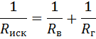
After the calculation for artificial earth electrodes is made, it is preliminarily determined whether there will be enough natural earth electrodes, and only then the required resistance of artificial earth electrodes is calculated

where Rclaim — resistance of artificial grounded electrodes, Rec — the same, natural, Rzu — normal resistance.
The earthing switches are welded with a steel strip 40x4 mm or with the same rod. These strips are laid in the ground at a depth of 0.7 m and form a common ground circuit.
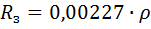
A steel rod 5 m long in normal soil (clay soil) at ρ = 100 ohm x m has a contact resistance of 22.7 ohm. To obtain a standard spread resistance of a single ground electrode of 22.7 ohms, the loop resistance is calculated, which consists of the resistance of the vertical Rc and horizontal electrodes in the form of a connecting strip Rd connected in parallel.
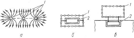
Rice. 1. Grounding devices: a — current lines of parallel connected grounded electrodes, b — grounding circuit of an independent transformer substation, c — the same built-in substation — 1 — grounding electrodes, 2 — internal grounding loop
The distance between the electrodes should be at least their length to avoid the phenomenon of their mutual shielding (Fig. 1 a), which leads to an increase in the resistance of the grounded electrode system. The contour is made in the form of a rectangle that encloses an electrical installation (for example, a free-standing substation or substation). If the electrical installation is built into the building, then the grounding circuit is made remotely and is connected to the internal circuit (inside the building) in at least two strips (Fig. 1. b, c).
In installations with isolated neutral and low grounding currents, the cross-section of the grounding wires is considered sufficient: copper 25, aluminum 35, steel 120 mm2... The minimum cross-section of round or strip steel of the grounding lines must be at least 100 m2 in installations up to 1000 V and 120 mm2 in installations above 1000 V.
For electrical installations with a voltage above 1000 V with low earthing currents, the resistance of the earthing device must meet the condition

where Uz is taken as 250 V if the earthing device is used only for installations with voltages above 1000 V, and Uh = 125 V if the earthing device is used simultaneously for installations with voltages up to 1000 V,
Azs — rated earth fault current, A.
In the calculations of grounding devices, the following simplified formulas are used, which determine the resistance of artificial grounding electrodes:
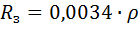
— for a concave rod electrode with a diameter of 10-12 mm, a length of about 5 m
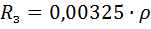
— for an angle steel electrode 50x50x5 mm and 2.5-2.7 m long
— for an electrode made of a pipe with a diameter of 50-60 mm and a length of 2.5 m
In installations with a voltage of up to 1000 V, the correct choice of grounding devices also provides conditions for quick and reliable disconnection of a network section (electrical installation) in the event of a short circuit.