Adiabatic negative and positive Hall effect
In a current-carrying wire placed in a magnetic field, a voltage is induced in a direction perpendicular to the directions of the electric current and the magnetic field. The phenomenon of the appearance of such a voltage is called the Hall effect, and the induced voltage itself is called the Hall voltage.
In 1879, the American physicist Edwin Hall (1855-1938), while working on his dissertation, discovered an interesting effect. He took a thin gold plate carrying a direct current and placed it in a magnetic field perpendicular to the plane of the plate. In this case, an additional electric field appeared between the edges of the plate. Later, this phenomenon was named after the discoverer. The Hall effect has found wide application: it is used to measure the induction of a magnetic field (Hall sensors), as well as to study the physical properties of conductive materials (using the Hall effect, one can calculate the concentration of current carriers and their sign ).
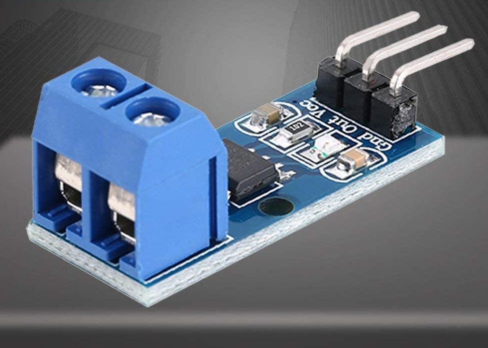
Hall Current Effect Sensor Module ACS712 5A
There are two types of electric current carriers—positive carriers moving in one direction and negative carriers moving in the opposite direction.
Negative carriers moving in a certain direction through a magnetic field experience a force that tends to divert their motion from a straight path. Positive carriers traveling in the opposite direction through the same magnetic field are deflected in the same direction as negative carriers.
As a result of such a deviation of all current carriers under the influence of Lorentz forces to the same side of the conductor, a carrier population gradient is established, and on one side of the conductor the number of carriers per unit volume will be greater than on the other.
The figure below illustrates the overall result of this process when there are equal numbers of carriers of two types.
Here, the potential gradients generated by carriers of two types are directed against each other, so that their influence cannot be detected when observed from the outside. If carriers of one type are more numerous than carriers of another type, then the carrier population gradient generates a Hall gradient potential, as a result of which the Hall voltage applied to the wire can be detected.

Adiabatic negative Hall effect. If only the electrons are charge carriers, then the temperature gradient and the electric potential gradient point in opposite directions.

Adiabatic Hall Effect. If only the holes are charge carriers, then the temperature gradient and the electric potential gradient point in the same direction
If the current through the wire under the influence of the Hall voltage is impossible, then between by Lorentz forces and through the Hall voltage equilibrium is established.
In this case, Lorentz forces tend to create a carrier population gradient along the wire, while the Hall voltage tends to restore a uniform population distribution throughout the volume of the wire.
The strength (voltage per unit thickness) of the Hall electric field directed perpendicular to the d current and magnetic field directions is determined by the following formula:
Fz = KzVJ,
where K.z — Hall coefficient (its sign and absolute value can vary significantly depending on the specific conditions); B — magnetic induction and J is the density of the current flowing in the conductor (the value of the current per unit of the cross-sectional area of the conductor).

The figure shows a sheet of material that conducts a strong current i when its ends are connected to a battery. If we measure the potential difference between the opposite sides, it will give us zero, as shown in the figure on the left. The situation changes when the magnetic field B is applied perpendicular to the current in the sheet, we will see that a very small potential difference V3 appears between the opposite sides as shown in the figure on the right.
The term «adiabatic» is used to describe conditions where there is no heat flow from the outside to or from the system under consideration.
There are layers of insulating material on both sides of the wire to prevent the flow of heat and current in the transverse direction.
Since the Hall voltage depends on the uneven distribution of carriers, it can only be maintained inside the body if the energy is supplied from some source external to the body.This energy comes from an electric field that creates an initial current in the substance. Two potential gradients are established in a galvanomagnetic substance.
The initial potential gradient is defined as the initial current density multiplied by the resistance of the substance, and the Hall potential gradient is defined as the initial current density multiplied by the Hall coefficient.
Since these two gradients are mutually perpendicular, we can consider their vector sum, the direction of which will be deviated by some angle from the direction of the original current.
This angle, the value of which is determined by the ratio of the forces of the electric field oriented in the direction of the current and the electric field generated in the direction of the current, is called the Hall angle. It can be positive or negative with respect to the direction of the current, depending on which carriers are dominant—positive or negative.
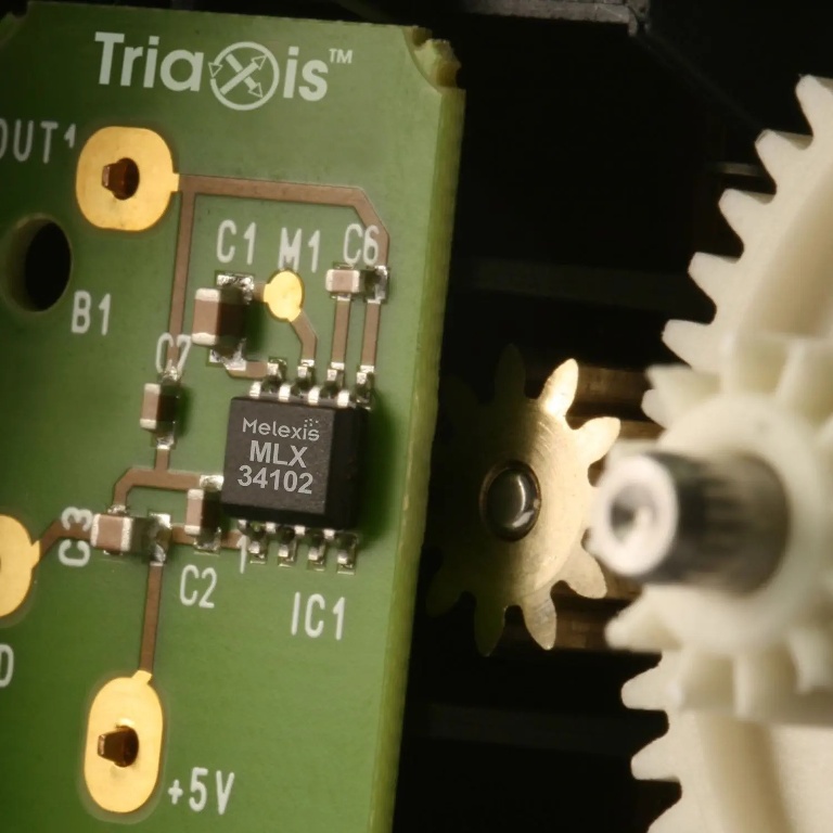
Hall Effect Proximity Sensor
The Hall effect is based on the mechanism of influence of a carrier with predominant salinity, which depends on the general physical properties of the conducting substance. For metals and n-type semiconductors, electrons are carriers, for p-type semiconductors - holes.
The current-carrying charges are deflected to the same side of the wire as the electrons. If holes and electrons have the same concentration, they generate two opposite Hall voltages. If their concentrations are different, then one of these two Hall voltages predominates and can be measured.
For positive carriers, the Hall voltage required to counteract carrier deflections under the influence of Lorentz forces is opposite to the corresponding voltage for negative carriers. In n-type metals and semiconductors, this voltage may even change sign when the external field or temperature changes.
A Hall sensor is an electronic device designed to detect the Hall effect and convert its results into data. This data can be used to turn circuits on and off, can be processed by a computer, and can cause various effects provided by the device manufacturer and software.
In practice, Hall sensors are simple, inexpensive microcircuits that use magnetic fields to detect variables such as the approach, speed, or displacement of a mechanical system.
Hall sensors are non-contact, which means that they do not need to come into contact with any physical elements. They can generate a digital or analog signal, depending on their design and purpose.
Hall effect sensors can be found in cell phones, GPS devices, compasses, hard drives, brushless motors, factory assembly lines, automobiles, medical devices, and many Internet of Things gadgets.
Hall Effect Application: Hall sensors and Measurement of magnetic quantities