Selection of XLPE insulated cables
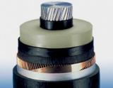 Selection of XLPE insulated cable (XLPE cable) is made according to the voltage, method and conditions of laying, current load. The cross-section of the cable must meet the requirement for thermal resistance at short-circuit currents.
By voltage, XLPE cables are traditionally divided into cables: low voltage (up to 1 kV), medium voltage (up to and including 35 kV), high voltage (110 kV and more).
XLPE insulated cables are laid in the ground (hidden seal) and air (open seal). Concealed laying is carried out in earthen trenches. Open laying on the territory of the enterprise is carried out in cable structures. Open laying of cables in the shops of industrial enterprises is carried out according to supporting structures made in the form of racks with shelves, wall shelves, etc.
Laying cable lines (CL) in a trench is one of the most common, simple and economical ways of laying.The depth of the cable line from the planning mark must be at least 0.7 m for cables with a voltage of up to 20 kV and at least 1 m for cables with a voltage of 35 kV and more.
When laying a large number of cables in one direction (more than 20), which is characteristic of energy-intensive industrial enterprises, cable structures are used: tunnels, galleries, overpasses, channels.
The layout of XLPE cables for open laying and in a trench is shown in fig. 1. The required distances between individual cables or their groups are also indicated here.
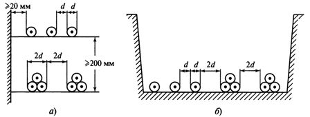
Rice. 1. The layout of XLPE insulated cables when laid outdoors (a) and in an earth trench (b)
Single-core cables can be laid horizontally in a plane with a clear distance between the cables not less than the cable diameter d. Single-core cables can be assembled in a three-phase group with delta back to back. The distance between adjacent groups of cables is at least 2d.
PvP, APvP cables are used for laying in the ground, regardless of the degree of soil corrosion, as well as in the air (open), provided that fire protection measures are provided.
The following types of cables are provided:
-
PvPu, ApvPu for laying in the ground on difficult sections of routes,
-
with longitudinal compaction of the grid (g) for laying in soils with high humidity, as well as in damp, partially flooded rooms,
-
PVV, APvV for laying in cable structures and industrial premises, as well as in dry soils,
-
PvVng, APvVng for group laying in cable structures and industrial premises,
-
PvVngd, APvVngd for laying facilities where requirements for reduced smoke and gas emissions are imposed (nuclear power plants, metro, large industrial facilities, high-rise buildings, etc.).
The cross-section of the current-carrying conductor of the cable is selected according to the economic current density and permissible heating. Normalized values of its economic current density are taken according to fig. 2. The resulting section is rounded to the nearest standard section.
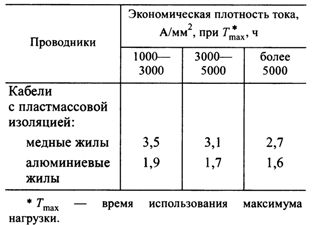
Rice. 2. Economic current density of wires
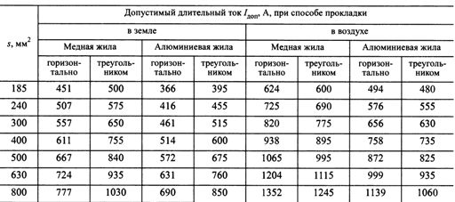
The permissible long-term temperature of the current-carrying conductor of the XLPE cable with a voltage of up to and including 110 kV is Tadd = 90 ° C. Permissible continuous currents of XLPE cables corresponding to the specified temperature Iadd are given in tables 1-4.
Table 1. Permissible continuous current Az additional single-core cables with XLPE insulation for a voltage of 6 kV
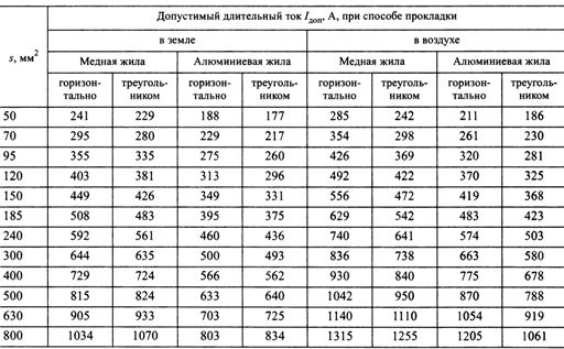
Table 2. Permissible continuous current Az additional single-core cables with XLPE insulation for a voltage of 10 kV
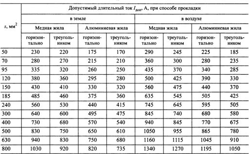
Table 3. Permissible continuous current Az additional single-core cables with XLPE insulation for voltage 35 kV
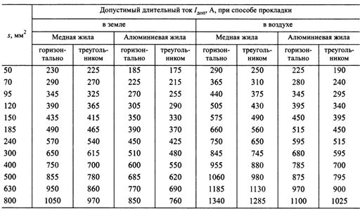
Table 4. Permissible continuous current Az additional single-core cables with XLPE insulation for voltage 110 kV
When laying the cable in air, it is assumed that the environment does not impede heat dissipation. When laying a cable in the ground, it is assumed that the soil in some sections of the cable route may dry out, worsening the conditions for the heat transfer of the cable. If the actual conditions differ from the calculated ones, the correction factors are entered from the Add value.
During the operation of cables, short-term overloads are allowed, for example, during the period of liquidation of an accident. In such modes, an increase in the temperature of the current-carrying conductor of XLPE cables with a voltage of up to 110 kV inclusive up to a value of Θp.a = 130 ° C is allowed. The permissible current values corresponding to the set temperature in overload modes are determined by multiplying the permissible continuous current by the overload factor kper:
-
when laying in a trench, kln = 1.23 (klenta = 1.17 for XLPE cables with a voltage of 110 kV),
-
with open laying in air kln = 1.27 (klenta = 1.2 for XLPE cables with a voltage of 110 kV).
The overload mode of XLPE cables is allowed no more than 8 hours per day, no more than 100 hours per year and no more than 1000 hours for the service life of the cable.
Cable cross-sections ° C with XLPE insulation should be checked for thermal resistance at short-circuit currents.