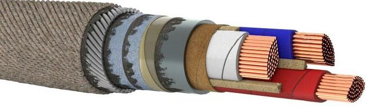
High voltage power cables with lead sheathed paper insulation and cable glands
Power cables are intended for the transmission and distribution of electricity in the area and for feeding it with current collectors.
Although cables are more expensive to install than overhead lines, they are increasingly being used as the preferred solution. Today, high voltage cables are mainly operated at voltage levels of 380 kV, 110 kV, 35 kV, 20 kV, 10 kV and 400 V.
While today almost only cables with plastic insulation are produced and XLPE sheath, the classic high-voltage cable is the so-called paper cable.
XLPE cables began to be widely laid before the 1980s, although in some countries this process began later. One particularly notable feature of this voltage level is the huge variety of alternative polymer cable types.
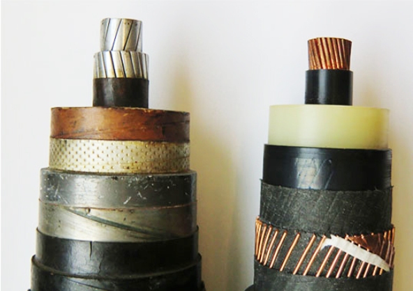
Paper-insulated power cables (left) vs. XLPE cable
Power cables with impregnated paper insulation
Paper-insulated lead cables have almost the same basic structure for voltage levels from 400 V to 35 kV.They have been used for power transmission since the introduction of the first power systems in the late 19th century.
20th century lead-sheathed armored power supply cable
For operating voltages up to and including 35 kV, such cables are made with insulation of oil rosin-impregnated cable paper in a lead sheath and armour, depending on the laying conditions.
Cables and wires laid on ships used in the mining and manufacturing industries and in agriculture are mainly made with rubber or plastic insulation in a flexible hose made of rubber or PVC.
Power cables are distinguished by the number of cores: one-, two-, three- and four-core. The conductors can be single or multi-wire, and in shape — round, sector, segmented and oval.
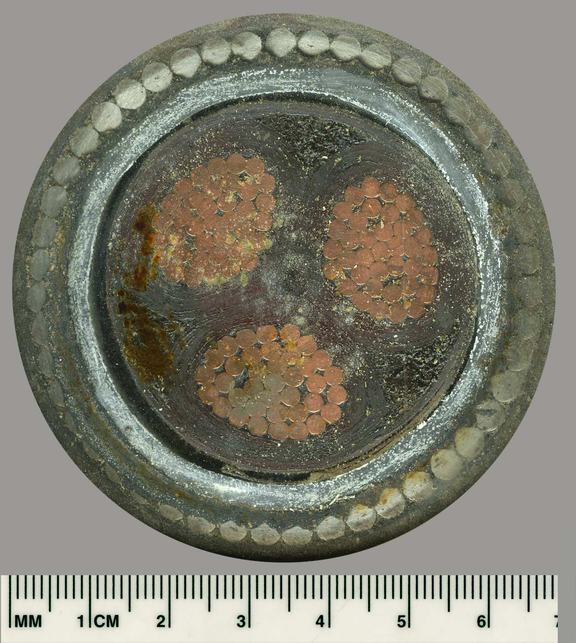
As mentioned above, a three-wire cable with a voltage of up to 6 kV appeared at the end of the XIX century. At first, it was a cable with round copper wires, a thick layer of paper-impregnated insulation on the wires, and the same thickness with a common (belt) layer of insulation on the insulated wires twisted together, that is, under a lead sheath.
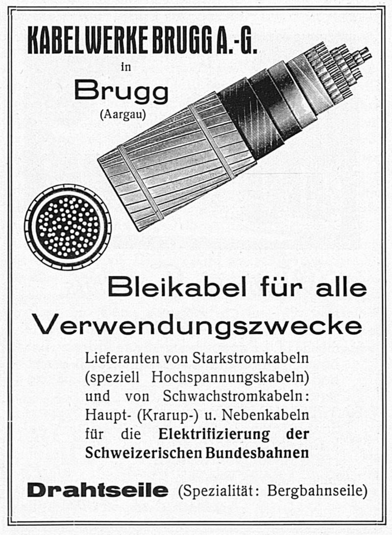
An example of lead cable in a Kabelwerke Brugg advertisement from 1927.
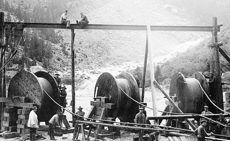
Laying of a 30 kV cable in Germany in 1928.
The development of the power cable goes along the lines of increasing the working voltage of the cable and the reliability of its operation, but not by further increasing the thickness of the insulation layer, but by improving the quality and improving the use of the insulation cable material in the cable.
The improvement of the economic indicators of the cable, i.e.above all, the reduction of its price is determined by the saving of basic materials due to their better use and improvement of the technological process (reduction of the production cycle, reduction of waste and rejects in production).
In the 1920s, round conductors in multicore power cables were replaced by segment and sector conductors, as the level of cable production had increased so much by this time that it became possible to produce reliable power cables with non-round conductors up to 10 kV inclusive.
The main type of impregnated paper power cable is the sector cable.
This cable has an insulating layer on each core (phase insulation) and a common insulating layer over the three insulated cores twisted together (belt insulation). Such a cable is called a cable with belt insulation or, according to the type of electric field in it, a cable with non-radial field, and by the type of impregnation - cable with viscous impregnation.
To designate a cable of this type, symbols (brands) are used depending on the type of shield and outer cover, for example:
- SG — cable without armor and caps over the lead,
- CA — a layer of asphalt is applied to the lead sheath,
- SB — above the lead is an armor of two steel strips and a cover of bitumen-impregnated cable yarn (jute),
- SBG — same as previous design but without jute covering over bumper,
- OP and SK — cable with an armor of flat or round wires.
The first letter of the brand indicates the presence of a shell, and the last indicates the type of protective covers.
In order to save lead by reducing the diameter in multi-core power cables (two-, three- and four-core), the conductors of the cable are made not round, but in the shape of a sector or segment.
A three-core cable with sector conductors is approximately 15% smaller in diameter than a cable with round conductors of the same cross-section. The saving of lead resulting from the introduction of sector conductors in three-conductor cables can be estimated at an average of 20%.
The conductors of a three-phase cable can be in the form of an oval approaching an ellipse. The advantage of this vein shape is that the oval vein does not have such sharp corners as the sector vein.
The use of oval conductor in 35 kV high-voltage cables can provide some compensation for thermal changes in the impregnating composition in the insulation layer of the cable and thus improve the quality of the cable.
The main insulating materials from which the insulating layer of the power cable is made in the cable factory are cable paper and reading compound.
The impregnation of the paper layer of the cable is carried out in order to replace the air in the paper and between the layers of paper tapes with mineral oil or some other impregnating compound that is stronger in electrical connection.
The role of the paper is not only to hold the impregnating compound. The presence of paper in the insulation layer of the cable makes it possible to obtain an insulation layer whose breaking strength is approximately 3 times higher than the breaking strength of the impregnating mixture.
The cable paper used for the production of the insulation layer of power cables must have certain mechanical properties that ensure a tight overlap of paper strips on the cable core, physical properties necessary for the proper implementation of the impregnation process, and must not contain impurities , which reduce the electrical properties of the paper after impregnation.
The construction of the 20 and 35 kV cable with belt insulation cannot provide sufficient reliability in operation, mainly due to the presence of tangential gradient components in the cable insulation caused by the non-radiality of the electric field.
To this voltage, a structure with three lead veins twisted into a common strip armor, conventionally designated by the brand OSB, is applied. This design was first proposed in 1923 by A. Yakovlev and S. M. Bragin.
High-voltage cables for voltages above 20 kV have always been produced as a single-core cable, i.e. with a radial electric field, since in this case the reliability of the cable at high voltage is of particular importance.
For 110 and 220 kV they are mainly used oil filled cables the main feature of which is that the paper insulation of this cable is impregnated with low viscosity mineral oil, which can easily move along the cable along the central hollow core under the influence of the excess pressure created in the cable.
When the temperature of the cable changes, the freely moving oil makes it possible to compensate with the help of power equipment the temperature changes in the volume in the insulating layer, which in the cable with viscous impregnation lead to the formation of voids and destruction.
The presence of a hollow core makes it possible to dry and feed the cable in production so that practically no bubbles and gas inclusions remain in it.
In production, the cable is wound on a drum and connected to a special oil tank under a certain positive pressure. Thanks to this device, gas inclusions do not form in the cable, even with significant temperature changes.
Modern cable OSB-35 3×120 for voltage 35 kV
Cable seals
Cable lugs and connectors are provided to allow cables to be connected to other equipment or to each other.
Since the cables are made to a limited length, connecting fittings — so-called cable glands — are required. The job of the cable box is to connect the two ends of the cable to each other.
A demonstration of a 30 kV cable link from the Leipzig Museum which, when opened, shows how such a cable link works:
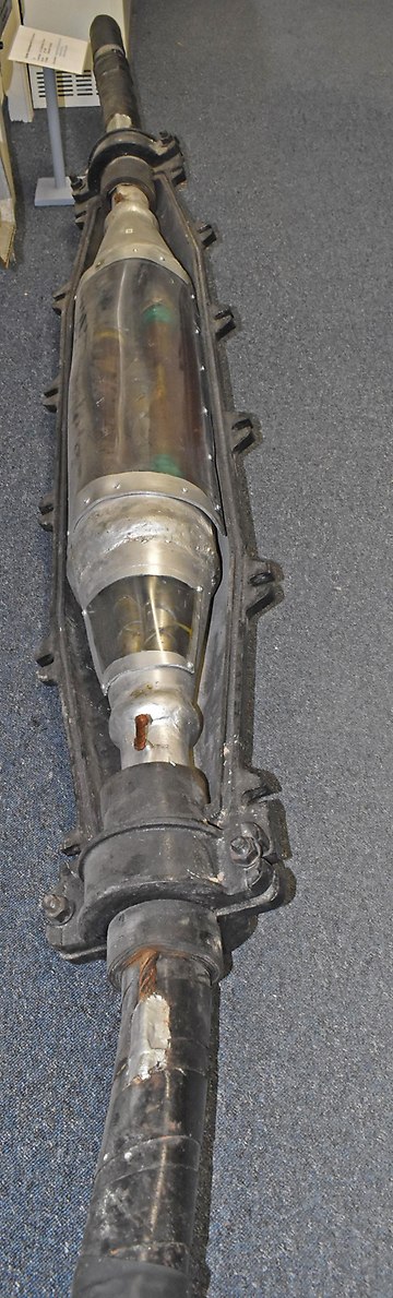
The direct connection of the aluminum wire is welded and machined with an aluminum file. In the case of copper wires, the so-called soldering sleeves are placed, cable cores and soldered.
The bare metal conductors are hand-wrapped with 10 to 30 mm wide oil paper until the insulation thickness is 2.5 times the cable insulation thickness.
Before winding, the cable mixture and the paper must be heated to 130 degrees so that the moisture can boil off. Open coal stoves were used for this. Of course, this was only possible outdoors.
To prevent moisture from entering the bushings, a factory-made inner bushing of lead or galvanized steel is used to connect the lead sheaths and solder them tightly.
Shortly before the end of the soldering process, cable compound is poured into the hole to avoid air pockets.
When carrying out the impregnation process of the power cable, all measures must be taken to evaporate the moisture remaining in the insulation layer before impregnation. and impregnate the entire insulation layer of the cable as completely as possible, minimizing air inclusions that may form in the insulation layer during NS whispers.
The impregnating compound must undergo periodic cleaning of mechanical impurities, vacuum treatment to remove moisture accumulated during the impregnation of the cable, and degassing to remove gas (air) dissolved in it.
Before the so-called "lead inner sleeve" is enclosed in a cast steel casing and filled with resin insulation, metal connections must be made between the steel strip reinforcement and the lead sheath.
After cooling for at least 3 hours, the installed socket can be used for a very long time (30 years or more).
For more information on the device and technology for installing cable seals for power cables, see here:Power cable connectors