Reactive power compensation in installations with gas discharge lamps
 If there are no special compensating capacitors in the circuit, then the power factor of the fluorescent lamp - ballast set when connected to the network is very low and is in the range of 0.5 - 0.55. In circuits with the sequential inclusion of two lamps (for example, a control device of the type 2ABZ-40), the power factor reaches 0.7, and in circuits with two lamps operating on the principle of "split phase" (for example, a control device of the type 2UBK-40 ) — 0.9 — 0.95.
With a low power factor, the currents in the network increase, which may require an increase in the cross-section of the wires, the nominal data of the network devices and the power of the transformers. Network losses also increase somewhat. For these reasons, PUE until recently required that the power factor be increased to 0.95 already in the places where the lamps are installed.
In principle, however, both individual reactive power compensation — directly at the lamps — and group compensation, when the capacitors are mounted on the shields and serve a whole group of lamps, are possible.
Group compensation has certain advantages: group capacitors can be more reliable and more durable than the currently used individual random capacitors that are not specifically designed for the given application. According to some calculations, group compensation is also more economical than individual compensation.
The feasibility of using one or the other compensation system is subject to further study and the solution to the problem will depend in particular on what new types of group and individual capacitors will be adopted by the industry.
Meanwhile, when ballasts are used almost exclusively in our installations according to a two-lamp starting circuit, the question of compensation is solved, so to speak, automatically: the same capacitors that serve to create a leading current in the lamp circuit also provide an increase in the coefficient of power to about 0.92.
Both individual and group reactive power compensation is used for MGL and DRL lamps.
The DRL — PRA lamp set has a power factor of about 0.57, which, as noted above, can result in a heavier grid. Reactive power compensation can relieve the network, but in turn involves the installation of relatively expensive individual or group capacitors.
According to the available data, in order to increase the power factor to 0.9 — 0.95 in 220 V, 50 Hz networks with arc lamps, it is necessary to install capacitors with the following powers (per lamp):
Lamp power, W 1000 750 500 250 Capacitance capacitors, μF 80 60 40 20
Capacitors of this capacity are not currently available, which limits the use of individual compensation.Of those produced by the industry, the most suitable are metal-paper capacitors of the MBGO type with a capacity of 10 μF, a voltage of 600 V. These capacitors must be connected in parallel and installed in steel boxes (for example, for a lamp with a power of 1000 W, it is necessary box with dimensions of 380x300x200 mm) together with discharge resistors that ensure rapid discharge of the capacitors after they are turned off.
The discharge resistance R is determined by the formula, Ohm:
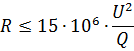
in which the reactive power of the capacitor Q, kvar, is found by the ratio

where C is the capacitance of the capacitor, μF; U — capacitor terminal voltage, kV.
For an MBGO capacitor with a capacitance of 10 μF, the reactive power Q is 0.15 kvar. For 1000 W lamps a carbon coated resistance of 620,000 ohms can be accepted, for 750 watt lamps a resistance of 825,000 ohms.
In group-compensated installations, the required capacitor power Q can be determined by the formula
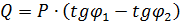
where P — installed power, kW, including ballast losses; φ1 and φ2 are the phase shift angles corresponding to the desired (φ2) and initial (φ1) power factor values.
To increase the power factor from 0.57 to 0.95 for every 1 kW of installed power, 1.1 kvar capacitors are required. With group compensation, three-phase paper oil capacitors of the KM-0.38-25 type, with a capacity of 25 kvar, as well as others with a lower power, for example, 10 kvar, can be used.
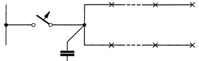
Rice. 1. A possible group line connection scheme with group line power factor compensation
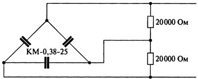
Rice. 2. Scheme of inclusion of discharge resistances with capacitor KM-0.38-25
Each 25 kvar capacitor is sufficient for a 22 kW group including ballast losses. The groups can be branched behind the capacitor plant as shown in fig. 1. For lines with KM-0.38-25 capacitors, the setting of the machine breaker does not exceed 40 A, and the current of each of the parallel lines is 36 A.
The discharge resistance for capacitors KM-0.38-25, calculated by the first formula, should not exceed 87,000 ohms. Each capacitor can be equipped with one tube resistance of type U1 with a power of 150 W, a resistance of 40,000 Ohm, with two sections of 20,000 Ohm connected according to the scheme of fig. 2.
Capacitors along with resistors are mounted near shields in steel cabinets, usually three to five in a cabinet. The dimensions of the cabinet for five capacitors are 1250 x 1450 x 700 mm.
Group compensation of reactive power in a substation can be done with the same KM capacitors assembled in batteries and using incoming cabinets to connect them to the substation busbars.
Comparative calculations made by "Tyazhpromelectroproject" showed that the option with reactive power compensation along the group lines of the panels is economically almost equivalent to the option without reactive power compensation. However, some preference may be given to the compensated option, which has additional advantages on the high voltage side of the supply. Moreover, in all cases where the lack of compensation leads to the need to increase the power of the transformer, the feasibility of compensation is indisputable.
It is recommended to refuse reactive power compensation in cases where an overcompensated load is connected to the transformer or where there is overcompensation on the high voltage side of the utility supply.
From the foregoing it is clear that the question of reactive power compensation in lighting networks cannot be solved in isolation from the whole spectrum of power supply problems and without detailed consideration of local conditions.
It may be added that if the supply lighting networks are very short, the installation of capacitors near the group screens hardly reduces the consumption of conducting metal, although it may lead to a reduction in the number of groups. Depending on the size of the workshop and the lighting control requirements, the latter may or may not be significant.
Thus, in a number of cases, the solution to the question of the need and methods of reactive power compensation in installations with DRL lamps is entirely within the competence of electricity suppliers.
It will be possible to return to the question of the expediency of individual reactive power compensation after the development and development by industry of special reliable capacitors for DRL lamps, durable and cheap; when using capacitors such as MBGO or the like, individual compensation is obviously inappropriate. However, one must always keep in mind the important operational advantage of installing capacitors in the control set or usually near the lamps, which is to turn off the capacitors at the same time as the lamps .
Some companies now supply ballasts with compensating capacitors.With a reliable design of the latter, this is, of course, very convenient.