Asynchronous electric motors with a wound rotor
Currently, asynchronous motors account for at least 80% of all electric motors produced by industry. These include three-phase asynchronous motors.
Three-phase asynchronous electric motors are widely used in automation and telemechanics devices, household and medical devices, sound recording devices, etc.
Advantages of asynchronous electric motors
The wide use of three-phase asynchronous motors is due to the simplicity of their design, reliability in operation, good operational properties, low cost and ease of maintenance.
The device of asynchronous electric motors with a wound rotor
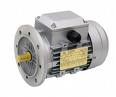 The main parts of any induction motor are the stationary part, the stator, and the rotating part, called the rotor.
The stator of a three-phase induction motor consists of a laminated magnetic circuit pressed into a cast frame. On the inner surface of the magnetic circuit there are channels for laying the winding wires. These wires are the sides of multi-turn soft coils that form the three phases of the stator winding.The geometric axes of the coils are shifted in space relative to each other by 120 degrees.
The winding phases can be connected according to the scheme star or triangle depending on the mains voltage. For example, if the motor's passport states voltages of 220/380 V, then with a mains voltage of 380 V, the phases are connected via a "star". If the mains voltage is 220 V, then the windings are connected in a «delta». In both cases, the phase voltage of the motor is 220 V.
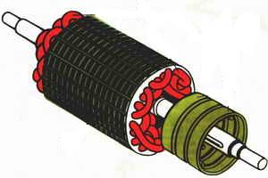
The rotor of a three-phase asynchronous motor is a cylinder made of stamped sheets of electrical steel and mounted on a shaft. Depending on the type of winding, the rotors of three-phase asynchronous motors are divided into squirrel and phase rotors.
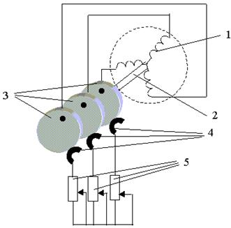
In asynchronous electric motors of higher power and special machines of low power, phase rotors are used to improve the starting and regulating properties. In these cases, a three-phase winding is placed on the rotor with the geometric axes of the phase coils (1) offset in space relative to each other by 120 degrees.
The phases of the winding are star-connected, and their ends are connected by three slip rings (3) mounted on the shaft (2) and electrically isolated both from the shaft and from each other. By means of brushes (4), which are in sliding contact with the rings (3), it is possible to include regulating rheostats (5) in the circuits of the phase winding.
An induction motor with a rotor has better starting and regulation properties, but is characterized by greater mass, dimensions and cost than an induction motor with a squirrel-cage rotor.
The principle of operation of asynchronous electric motors
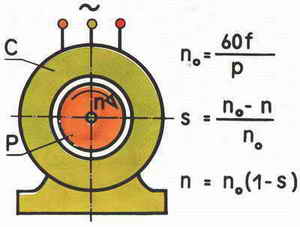
The principle of operation of an asynchronous machine is based on the use of a rotating magnetic field.When a three-phase stator winding is connected to the grid, it rotates magnetic fieldthe angular speed of which is determined by the frequency of the network f and the number of pole pairs of the winding p, i.e. ω1 = 2πf / p
Crossing the wires of the stator and rotor windings, this field induces an EMF in the windings (according to the law of electromagnetic induction). When the rotor winding is closed, its EMF induces a current in the rotor circuit. As a result of the interaction of the current with the resulting small field, an electromagnetic moment is created. If this moment exceeds the moment of resistance of the motor shaft, the shaft starts to rotate and sets the working mechanism in motion. Usually, the angular velocity of the rotor ω2 is not equal to the angular velocity of the magnetic field ω1, which is called synchronous. Hence the name of the motor asynchronous, that is, asynchronous.
The operation of an asynchronous machine is characterized by slip s, which is the relative difference between the angular velocities of the field ω1 and the rotor ω2: s = (ω1-ω2) / ω1
The value and sign of slip, depending on the angular velocity of the rotor relative to the magnetic field, determine the mode of operation of the induction machine. So in the ideal idle mode, the rotor and the magnetic field rotate at the same frequency in the same direction, slip s = 0, the rotor is stationary relative to the rotating magnetic field, the EMF in its winding is not induced, the rotor current and the electromagnetic moment of the machine are zero. At start-up, the rotor is stationary at the first instant of time: ω2 = 0, s = 1. Basically, the slip in the motor mode changes from s = 1 at start-up to s = 0 in the ideal idle mode.
When the rotor rotates at a speed ω2> ω1 in the direction of rotation of the magnetic field, the slip becomes negative. The machine goes into generator mode and develops the braking torque. When the rotor rotates in the direction opposite to the direction of rotation of the magnetic pole (s> 1), the induction machine switches to the opposite mode and also develops a braking torque. Thus, depending on the slip, a distinction is made between the modes of the engine (s = 1 ÷ 0), the generator (s = 0 ÷ -∞) and the opposite mode (s = 1 ÷ + ∞). Generator and counter commutation modes are used to stop induction motors.
See also: Starting a wound rotor motor