Tools and display devices
 Pointing devices or display elements are the basis of information display devices designed to convert an electrical signal into a visible form.
Light indicators - use the glow of an incandescent filament heated by an electric current. They are miniature lamps with an incandescent filament, illuminating colored cases (filters) of indicators and buttons or certain images, signs, symbols.
Electroluminescent indicators - the glow of some substances is used under the influence of an electric field. For example vacuum fluorescent indicators. They are multi-anode lamps with a cathode, emitting electrons, and a grid that controls the current of the indicator. Anodes are made in the form of synthesizing segments covered with phosphorus. When the electrons collide with the surface of the anodes, the phosphor of the required color glows. A separate supply voltage is applied to each anode.
Previously widely used, they are being displaced by other types of indicators. They allow obtaining a large number of elements and characters with different colors and high brightness.
Electron beam devices — based on the glow of phosphors when bombarded with electrons.
The most prominent representatives of cathode ray devices are cathode ray tubes (CRT). CRT is an electronic vacuum device that uses a beam of electrons concentrated in the form of a beam controlled by an electric and / or magnetic field and creates a visible image on a special screen (Fig. 1).
They are used in oscilloscopes — to monitor electronic processes, in television (kinescopes) — to convert an electrical signal containing information about the brightness and color of the transmitted image, in radar imaging devices — to convert electrical signals containing information about the surrounding space in a visible image.
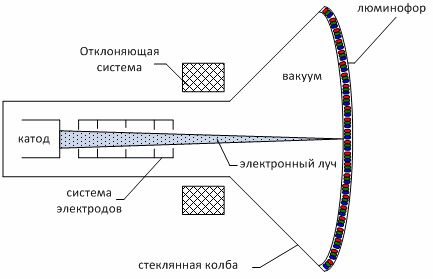
Figure 1 — Construction of an electron beam tube
They are intensively displaced by liquid crystal indicators: the production of CRT monitors is discontinued, CRT TVs are declining.
Gas Discharge (Ion) Devices - The gas glow is used for an electrical discharge.
They consist of a sealed cylinder with electrodes soldered into it (in the simplest case, anode and cathode — a neon lamp), and filled with inert gases (neon, helium, argon, krypton) at low pressure. When voltage is applied, gas glow is observed. The color of the glow is determined by the composition of the filling gas. Used to denote AC or DC voltages.
Today gas discharge devices plasma panels are used for production.
A plasma panel PDP (plasma display panel) is a matrix of cells enclosed between two panes of glass. Each cell is covered with phosphor (adjacent cells form triads of three colors — red, green and blue R, G, B) and filled with an inert gas — neon or xenon (Fig. 2).When an electric current is applied to the cell's electrodes, the gas transforms into a plasma state and causes the phosphor to glow.
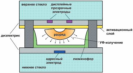
Figure 2 — Design of plasma panel cells
The main advantage of plasma panels is the large screen sizes — usually ranging from 42" to 65". In addition, individual panels can be assembled into large screens for use in concert halls, stadiums, squares, etc.
Plasma panels have a high contrast ratio (difference between black and white), a wide viewing angle and a wide range of operating temperatures.
Along with the advantages, there are also disadvantages: only large-sized panels, gradual "burning" of the phosphor, relatively high energy consumption.
Semiconductor indicators - the principle of operation is based on the emission of light quanta in the region of the p-n junction, to which a voltage is applied.
Distinguish:
— discrete (point) semiconductor indicators — LEDs;
— character indicators — to display numbers and letters;
— LED matrices.
LEDs or light emitting diodes (LED — Light Emission Diodes) have become widespread due to their compactness, the ability to receive any color of emission, the absence of a fragile glass bulb, low supply voltage and ease of switching.
The LED consists of one or more crystals (Fig. 3) emitting radiation and located in the same housing with a lens and a reflector that forms a directed light beam in the visible or infrared (invisible) part of the spectrum.
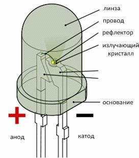
Figure 3 — Construction of an LED
An example. Figure 4 shows a diagram of switching the LED to a 12 V supply.The voltage drop across the diode when connected directly is about 2.5 V, so it is necessary to turn on the quenching resistor in series. To ensure sufficient brightness, the diode current should be on the order of 20 mA. It is necessary to determine the resistance of the damping resistor R.
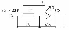
Figure 4 — Scheme for turning on the LED
To do this, we determine the voltage that must drop (turn off) on the resistor: UR = UP — UVD = 12 — 2.5 = 9.5 V
To provide a given current in the circuit at a given voltage, according to Ohm's Law we determine the resistance value of the resistor: R = UP / I = 9.5 / 20 • 10-3 = 475 Ohm
The nearest larger standard resistor value is then selected. For this example, you can choose the closest value of 470 ohms.
Powerful LEDs are used as light sources in indoor and outdoor lighting, floodlights, traffic lights and car headlights. Inertial performance makes LEDs indispensable when high performance is required.
Combining seven LEDs into one housing allows you to create a seven-segment character indicator that allows you to display 10 numbers and some letters. In the indicator shown in the diagram (Fig. 5), the anode is common to the diodes, the supply voltage is supplied to it, and the cathodes are connected to electronic switches (transistors) that connect them to the box. Usually the character indicator is controlled by a microcircuit.
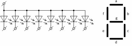
Figure 5 — Iconic semiconductor indicator
LED matrices (modules) — a certain number of LEDs made in the form of a complete block and with a control circuit. Dies are used for production LED screens (LED displays).
Liquid crystal displays (LCD) — based on the change in the optical properties of liquid crystals under the influence of an electric field.
Liquid crystals (LC) are organic liquids with an ordered arrangement of molecules characteristic of crystals. Liquid crystals are transparent to light rays, but under the influence of an electric field their structure is disturbed, the molecules are arranged randomly and the liquid becomes opaque.
According to the principle of operation, LCD displays are distinguished that work in transmitted light (through transmission) created by a backlight source (discharge lamps or LEDs) and in the light of any source (artificial or natural) reflected in the indicator (for reflection) . Working on light is used in monitors, mobile phone displays. Reflective indicators are found in meters, clocks, calculators, home appliance displays, and more.
In addition, a number of indicators are used with a switchable backlight in bright conditions and with the backlight turned on in low light to reduce power consumption.
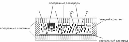
Figure 6 — Liquid Crystal Reflectance Indicator
Figure 6 shows a reflective LCD display. Between two transparent plates there is a layer of liquid crystal (thickness of the layer 10 — 20 µm). The upper plate has transparent electrodes in the form of segments, numbers or letters.
If there is no voltage to the electrodes, then the LCD is transparent, the light rays of the external natural lighting pass through it, are reflected by the lower mirror electrode and come back out — we see a blank screen.When a voltage is applied to any electrode, the LCD display below that electrode becomes opaque, light rays do not pass through that part of the liquid, and then we see a segment, number, letter, sign, etc. on the screen.
Liquid crystal indicators have a number of advantages, among which are very low power consumption, durability and compactness.
Today, LCD monitors (LCD monitors — liquid crystal display — liquid crystal monitors, TFT monitors — LCD matrix using thin-film transistors) are the main type of monitors and television receivers.