Electronic generators
 Generators are electronic devices that convert the energy of a direct current source into alternating current energy (electromagnetic oscillations) with various forms of the required frequency and power.
Electronic generators used in radio broadcasting, medicine, radar, are part of analog-to-digital converters, microprocessor systems, etc.
No electronic system is complete without internal or external generators that determine the pace of its operation. Basic requirements for generators — stability of the vibration frequency and the ability to remove signals from them for further use.
Classification of electronic generators:
1) according to the form of the output signals:
— sinusoidal signals;
— rectangular signals (multivibrators);
— linearly varying voltage signals (CLAY) or they are also called sawtooth voltage generators;
— special shape signals.
2) from the frequency of the generated oscillations (conditionally):
— low frequency (up to 100 kHz);
— high frequency (above 100 kHz).
3) by the excitation method:
— with independent (external) excitation;
— with self-excitation (autogenerators).
Autogenerator — a self-excited generator, without external influence, converting the energy of energy sources into continuous vibration, for example, a vibrating circuit.
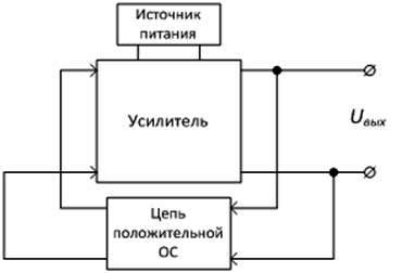
Figure 1 — Block diagram of the generator
Electronic generator circuits (Figure 1) are built according to the same schemes as amplifiers, only generators do not have an input signal source, it is replaced by a positive feedback signal (PIC). We remind you that feedback is the transfer of part of the output signal to the input circuit. The required waveform is provided by the feedback loop structure. To set the oscillation frequency, OS circuits are built on LC or RC circuits (the frequency determines the capacitor recharge time).
The signal generated in the PIC circuit is applied to the input of the amplifier, amplified by a factor K and sent to the output. In this case, part of the signal from the output is returned to the input through the PIC circuit, where it is attenuated by a factor of K, which will allow maintaining a constant amplitude of the output signal of the generator.
Oscillators with independent external excitation (selective amplifiers) are power amplifiers with the corresponding partial range, the input of which is an electrical signal from an oscillator. These. only a certain frequency band is amplified.
RC generators
To create low-frequency generators, operational amplifiers are usually used, such as a PIC circuit, RC circuits are installed to provide a given frequency f0 of sinusoidal oscillations.
RC circuits are frequency filters—devices that pass signals in a certain frequency range and don't pass into the wrong range.In this case, through the feedback loop, the amplifier is fed back to the input of the amplifier, which means that only a certain frequency or frequency band is amplified.
Figure 2 shows the main types of frequency filters and their frequency response (AFC). The frequency response shows the bandwidth of the filter as a function of frequency.
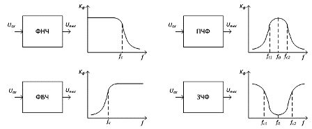
Figure 2 — Types of frequency filters and their frequency response
Types of filters:
— low-pass filters (LPF);
— high-pass filters (HPF);
— band pass filters (BPF);
— blocking frequency filters (FSF).
Filters are characterized by a cut-off frequency fc above or below which there is a sharp attenuation of the signal. Passbands and rejection filters are also characterized by the IFP (RFP non-pass) bandwidth.
Figure 3 shows a diagram of a sinusoidal generator. The required gain is set using the OOS circuit of resistors R1, R2. In this case, the PIC circuit is a bandpass filter. The resonant frequency f0 is determined by the formula: f0 = 1 / (2πRC)
To stabilize the frequency of the generated oscillations, quartz resonators are used as a frequency tuning circuit. A quartz resonator is a thin mineral plate mounted in a quartz holder. As you know, quartz has piezoelectric effect, which makes it possible to use it as a system equivalent to an electrical oscillating circuit and possessing resonant properties. The resonant frequencies of quartz plates range from a few kilohertz to thousands of MHz with frequency instability typically on the order of 10-8 and below.
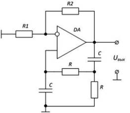
Figure 3 — Diagram of an RC sine wave generator
Multivibrators are electronic generators square wave signals.
The multivibrator in most cases performs the function of a master oscillator that generates trigger input pulses for subsequent nodes and blocks in a pulse or digital action system.
Figure 4 shows a diagram of an IOU-based symmetric multivibrator. Symmetrical — the pulse time of a rectangular pulse is equal to the pause time tpause = tpause.
The IOU is covered by positive feedback — a circuit R1, R2 acting equally at all frequencies. The voltage at the non-deflecting input is constant and depends on the resistance of the resistors R1, R2. The input voltage of the multivibrator is generated using OOS through the RC circuit.
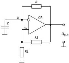
Figure 4 — Schematic of a symmetrical multivibrator
The output voltage level changes from + Usat to -Us and vice versa.
If the output voltage Uout = + Usat, the capacitor is charged and the voltage Uc acting on the inverting input increases exponentially (Fig. 5).
With the equality Un = Uc, there will be a sharp change in the output voltage Uout = -Us, which will lead to overcharging of the capacitor. When the equality -Un = -Uc is reached, the state of Uout will change again. The process is repeated.
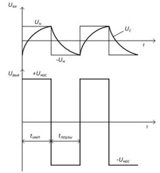
Figure 5 — Timing diagrams for multivibrator operation
Changing the time constant of the RC circuit results in a change charging and discharging time of the capacitor, and hence the oscillation frequency of the multivibrator. In addition, the frequency depends on the PIC parameters and is determined by the formula: f = 1 / T = 1 / 2t and = 1 / [2 ln (1 + 2 R1 / R2)]
If it is necessary to obtain asymmetric rectangular oscillations for t and ≠ tp, asymmetric multivibrators are used, in which the capacitor is recharged in different circuits with different time constants.
A single vibrator (waiting multivibrators) are designed to form a rectangular voltage pulse of the required duration when exposed to a short trigger pulse at the input. Monovibrators are often called electronic time delay relays.
There's more to the technical literature. the name of the one-shot is the waiting multivibrator.
A monovibrator has one long-term steady state, the equilibrium it is in before the trigger pulse is applied. The second possible state is temporarily stable. The univibrator enters this state under the action of a trigger pulse and can be in it for a limited time tv, after which it automatically returns to its initial state.
The main requirements for single-shot devices are the stability of the duration of the output pulse and the stability of its initial state.
Linear voltage generators (CLAY) form periodic signals that vary linearly (sawtooth pulses).
Sawtooth pulses are characterized by the duration of the working stroke tp, the duration of the return stroke to and the amplitude Um (Figure 6, b).
To create a linear dependence of voltage on time, the charge (or discharge) of a capacitor with a constant current is most often used. The simplest scheme of CLAY is shown in figure 6, a.
When the transistor VT is closed, the capacitor C2 is charged by the power supply Up through the resistor R2. In this case, the voltage in the capacitor and therefore at the output increases linearly.When a positive pulse arrives at the base, the transistor opens and the capacitor rapidly discharges through its low resistance, which provides a rapid reduction of the output voltage to zero—and vice versa.
CLAY is used in beam scanning devices in CRTs, in analog-to-digital converters (ADCs), and other conversion devices.
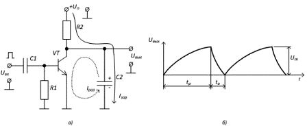
Figure 6 — a) The simplest scheme for the formation of linearly changing voltage b) Time diagram of trion pulses.