Rectifiers with voltage multiplier
A rectifier is a device for converting alternating current to direct current, as well as for stabilizing and regulating a rectified voltage.
In the diagram of fig. 1, and the transformer does not have a double-voltage boost winding with a midpoint, but at the same time full wave rectification the rectifier doubles the voltage.
During the first half-cycle, through the diode D1, the voltage across which is direct, the capacitor C1 is charged approximately to the amplitude voltage of the secondary winding. During the second half-cycle, the forward voltage will be across diode D2 and capacitor C2 is charged across it in the same way.
Capacitors C1 and C2 are connected in series and the total voltage across them is approximately equal to twice the amplitude voltage of the transformer. The same maximum reverse voltage will be across each diode. Simultaneously with the charging of the capacitors C1 and C2, they are discharged through the load R, as a result of which the voltage in the capacitors decreases.
The lower the load resistance R, that is, the greater the load current and the lower the capacity of capacitors C1 and C2, the faster they discharge and the lower the voltage on them. Therefore, it is impossible to practically double the voltage. With a capacitor capacity of at least 10 μF and a load current of no more than 100 mA, a voltage can be obtained that is 1.7 or even 1.9 times higher than that given by the transformer.
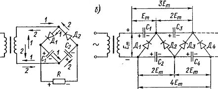
Rice. 1. Rectifier circuits with doubling (a) and quadrupling (b) voltage
The advantage of the circuit is that the capacitors smooth out ripples in the rectified current.
Rectifier circuits with a voltage multiplier can be applied any number of times. In fig. 1b shows a circuit that triples the voltage and has four diodes and four capacitors. In odd half cycles, the capacitor C1 is charged through the diode D1 almost to the peak value of the voltage of the transformer Et. The charged capacitor C1 is itself a source.
Therefore, even in half-cycles for which the polarity of the transformer voltage will be reversed, the capacitor C2 is charged through the diode D2 to approximately twice the voltage 2Em. This voltage is the maximum value of the total voltage of the series-connected transformer and capacitor C1.
Similarly, the capacitor C3 is charged in odd half-cycles through the diode D3 also to a voltage of 2Em, which is the total voltage of the series-connected C1, the transformer and C2 (it must be borne in mind that the voltages of C1 and C2 act on each other).
Reasoning similarly further, we find that capacitor C4 will charge even half-cycles through diode D4.Again to the voltage 2Em which is the sum of the voltages of C1, C3, the transformer and C2. Of course, the capacitors are charged to the specified voltages gradually over several half-cycles after the rectifier is turned on. As a result, from capacitors C1 and C4 you can get a quadruple voltage 4Et.
Simultaneously with capacitors C1 and C3 you can get a triple voltage ZET. If we add to the circuit more capacitors and diodes connected according to the same principle, then from a number of capacitors C1, C3, C5, etc., voltages will be obtained that increase by an odd number of times (3, 5, 7, etc. n.), and from a number of capacitors C2, C4, C6, etc. it will be possible to obtain voltages increased by an even number of times (2, 4, 6, etc.).
When the load is switched on, the capacitors will discharge and the voltage on them will decrease. The lower the load resistance, the faster the capacitors will discharge and the voltage on them will decrease. Therefore, with insufficiently large load resistances, the use of such schemes becomes irrational.
In practice, such schemes provide effective voltage multiplication only at low load currents. Of course, you can get higher currents if you increase the capacitance of the capacitors. The advantage of the above scheme is the ability to obtain high voltage without a high voltage transformer. In addition, the capacitors must have an operating voltage of only 2Em, no matter how many times the voltage is multiplied, and each diode operates at a maximum reverse voltage of only 2Em.
Rectifier parts
Diodes are selected according to their main parameters: maximum rectified current I0max and limiting reverse voltage Urev. In the presence of a capacitor at the input of the filter, the effective value of the voltage of the secondary winding of the transformer U2 in all rectifier circuits, except for the bridge circuit, should not exceed — 35% of the value of Urev. In a zero-point full-wave circuit, the voltage U2 refers to half of the winding. In the bridge circuit, y should not exceed 70% of the Urev value.
To correct higher voltages, the appropriate number of diodes are connected in series.
When germanium and silicon diodes are connected in series, they are necessarily manipulated with resistors of the same resistance on the order of tens or hundreds of kilo-ohms (Fig. 2). If this is not done, then due to a significant spread in the reverse resistance of the diodes, the reverse voltage is unevenly distributed between them and breakdown of the diode is possible. And in the presence of shunt resistors, the reverse voltage is practically equally divided between the diodes.
Parallel connection of diodes in order to obtain large currents is undesirable, because due to the spread of parameters and characteristics of individual diodes, they will be unevenly loaded with current. To equalize the currents in this case, equalizing resistors are connected in series with individual diodes, the resistances of which are chosen empirically.
For rectifier transformers, the primary winding usually has several sections switching to 110, 127 and 220 V mains voltage.
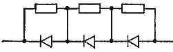
Rice. 2. Series connection of semiconductor diodes
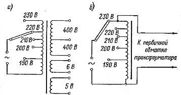
Rice. 3.Ways to adjust voltage
The secondary winding is designed for the required voltage. With a full-wave circuit, it has a midpoint output. To reduce interference from the network in the rectifier transformers feeding the receivers, a shielding coil is placed between the primary and secondary windings, one end of which is connected to a common negative.
Chokes for the filter, as a rule, have in the core diamagnetic gap to eliminate magnetic saturation, which leads to a reduction in inductance. The resistance of the inductor coil to direct current is usually equal to several tens or hundreds of ohms. Part of the rectified voltage falls on it and on the step-up winding of the transformer.
A switch and a fuse are installed in the mains winding circuit to automatically shut down the rectifier in the event of an emergency. If, for example, the filter capacitor is broken, then a short circuit will occur in the rectified current circuit. The primary current will become significantly higher than normal and the fuse will blow. Without it, the transformer can burn out. In addition, such a short circuit is very dangerous for the diode, which can be destroyed by overheating with too much current.
Sometimes the primary winding of the transformer is made with outputs for different voltages, for example 190, 200, 210, 220 and 230 V, so with the help of the switch it was possible to maintain an approximately constant voltage of the rectifier with using the switch during fluctuations in the mains voltage (Fig. 3, a).Another way to regulate is to include a regulating autotransformer that has outputs for different voltages and a switch.
Turn on regulating autotransformer allows, when the mains voltage is lowered, to supply normal voltage to the primary winding of the power transformer (Fig. 3, b). There are also special adjusting autotransformers for mains voltage 127 and 220 V, allowing smooth adjustment of the voltage from 0 to 250 V.
When working with a rectifier, especially if it gives high voltage, precautions must be taken, because injuring a person with a voltage of several hundred volts is life-threatening.
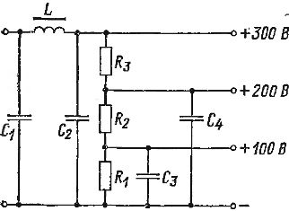
Fig. 4. Switching on a divider for three different voltages
All high voltage parts of the rectifier must be protected from accidental contact. Never touch any part of the rectifier in operation. All connections to or changes to the rectifier circuit are made when the rectifier is off and the filter capacitors are discharged. It is useful to include a neon lamp on the rectified voltage as an indicator (pointer) of high voltage. Its glow indicates the presence of high voltage.
The neon lamp is switched on by a limiting resistor with a resistance of several tens of kilo-ohms. The presence of a constant load in the form of such a lamp protects the filter capacitors from overvoltage breakdown. The latter can happen if the rectifier is running at idle speed. With no load, there is no voltage drop inside the rectifier and therefore the voltage across the filter capacitors will be maximum.
Read also: Voltage resonance