Logical devices
 Logical algebra or Boolean algebra is used to describe the laws of operation of digital circuits. The algebra of logic is based on the concept of an "event" that may or may not happen. An event that has occurred is considered true and a logic level «1» is expressed, an event that has not occurred is considered false and a logic level «0» is expressed.
The event is influenced by variables and they influence according to a certain law. This law is called a logical function, the variables are arguments... Che. the logical function is the function y = f (x1, x2, … xn), which takes the values «0» or «1». The variables x1, x2, … xn also have values «0» or «1».
Algebra of logic — a branch of mathematical logic that studies the structure of complex logical statements and ways of establishing their truth by algebraic methods. In the formulas of logical algebra, the variables are logical or binary, that is, they take only two values - false and true, which are denoted by 0 and 1, respectively. Every computer program contains logical operations.
Devices designed to form functions of the logic algebra are called logic devices... A logic device has any number of inputs and only one output (Fig. 1).
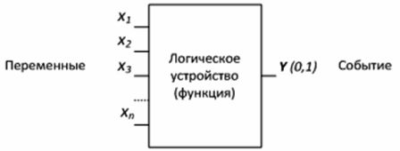
Figure 1 — Logic device
For example, an electronic combination lock includes a logic device for which event (y) is the opening of the lock. For the event (y = 1) to occur, i.e. the lock has opened, it is necessary to define the variables — ten buttons on the numeric keypad. Certain buttons must be pressed ie. take the value «1» and at the same time press in a certain sequence — a logical function.
It is convenient to represent any logical function in the form of a state table (truth table), where possible combinations of variables (arguments) and the corresponding value of the function are recorded.
Logic devices are built on logic gates that perform a specific function. The basic logic functions are logical addition, logical multiplication, and logical negation.
1) OR (OR) — logical addition or division (from English disjunction — interruption) — a logical unit appears at the output of this element when a unit appears at least at one of the inputs. The output will be logic zero only when there is a logic zero signal on all inputs.
This operation can be accomplished using a contact circuit with two contacts connected in parallel. «1» at the output of such a circuit will appear if at least one of the contacts is closed.
2) AND (AND) — logical multiplication or connection (from the English union — connection, & — ampersand) — at the output of this element, the signal of a logical unit appears only when a logical unit is present at all inputs.If at least one input is zero, then the output will also be zero.
This operation can be carried out by a contact circuit consisting of contacts connected in series.
3) NOT — logical negation or inversion indicated by a dash above a variable — the operation is performed on one variable x and the value of y is the opposite of that variable.
The operation can NOT be performed using a normally closed contact of the electromagnetic relay: there is no voltage on the relay coil (x = 0) — the contact is also closed at the output «1» (y = 1). In the presence of voltage on the relay coil (x = 1), the contact is also open on the «0» output (y = 0).
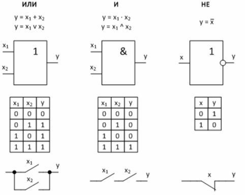
Figure 2 — Basic logic functions and their implementation
Logic devices use different logic gates. Particularly important are two universal logical operations, each of which is capable of independently forming any logical function.
4) NAND — Schaefer function.
5) OR NOT — Punch function.
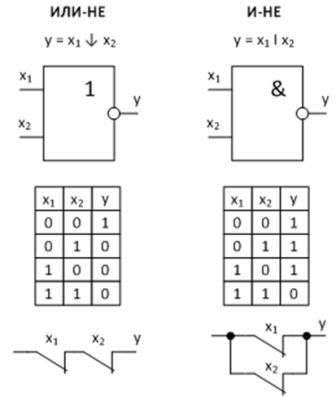
Figure 3 — Universal logic functions and their implementation
Example: Security alarm circuit based on logic elements. Generator G generates a siren signal, feeding it to the amplifier stage through the logic element «AND» of the microcircuit DD2. When the protective switches S1 — S4 are closed, the level «0» acts on the inputs of the element DD1 — the level «0» is on the lower input of the element «I» DD2, which means that the gate of the transistor VT is also «0».
In the case of opening at least one of the switches, for example S1, the input of the element DD1 through the resistor R1 will receive a voltage of level «1», which will cause the appearance of «1» at the second input of the element «AND» DD1.This will allow the signal from the generator G to pass to the gate of the transistor whose load is the speaker.
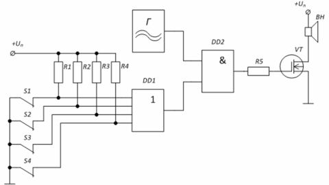
Figure 4 — Alarm protection scheme
Complex digital circuits are built by repeating basic logic circuits over and over. The tool for such construction is Boolean algebra, which in terms of digital technology is called logic algebra. Unlike a variable in ordinary algebra, a boolean variable has only two values, which are called boolean zero and boolean one.
Logical zero and logical one are denoted by 0 and 1. In logical algebra, 0 and 1 are not numbers, but logical variables. In logical algebra, there are three basic operations between logical variables: logical multiplication (conjunction), logical addition (disjunction), and logical negation (inversion).
Electronic circuits performing the same logical function, but assembled with different elements, differing in power consumption, supply voltage, values of high and low output voltage levels, signal propagation delay time and load carrying capacity.
See also on this topic: AND, OR, NOT, AND-NOT, OR-NOT logic gates and their truth tables