AND, OR, NOT, AND-NOT, OR-NOT logic gates and their truth tables
An electrical circuit designed to perform any logical operation on input data is called a logic element. The input data is represented here in the form of voltages at different levels, and the result of a logic operation on the output is also obtained in the form of a voltage at a certain level.
In this case, the operands are passed in binary notation — the input of the logic element accepts signals in the form of high or low voltage, which essentially serve as input data. So, a high-level voltage—that's a logic 1—means the true value of the operand, and a low-level voltage of 0—the false value. 1 - TRUE, 0 - FALSE.
Logical element — an element that implements a certain logical connection between input and output signals. Logic elements are commonly used to build computer logic circuits, discrete circuits for automatic control and management.All types of logic elements, regardless of their physical nature, are characterized by discrete values of input and output signals.
Logic gates have one or more inputs and one or two (usually reversed) outputs. The values of «zeros» and «ones» of the output signals of logic elements are determined by the logic function performed by the element, and the values of «zeros» and «ones» of the input signals, which play the role of the independent variables. There are elementary logic functions that can be used to construct any complex logic function.
Depending on the arrangement of the circuit of the element, on its electrical parameters, the logic levels (high and low voltage levels) at the input and output have the same values for high and low (true and false) states.
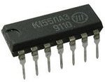
Traditionally, logic elements are produced in the form of special radio components — integrated circuits. Logical operations such as join, disjoin, negate, and add modulo (AND, OR, NOT, exclusive OR) are the basic operations performed on logical elements of basic types. Let's take a closer look at each of these types of logic gates.
Logical element "AND" — connection, logical multiplication and AND
An "AND" is a logical element that performs a concatenation or logical multiplication on the input data. This element can have from 2 to 8 (the most common in production "AND" elements with 2, 3, 4 and 8 inputs) inputs and one output.
Symbols of logic elements «AND» with different number of inputs are shown in the figure. In the text, a logic element «And» with one or another number of inputs is designated as «2I», «4I», etc. — element "AND" with two inputs, with four inputs, etc.
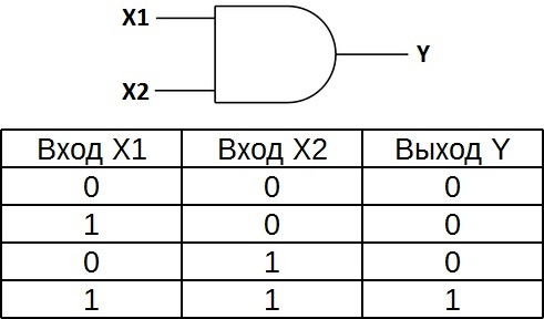
The truth table for element 2I shows that the output of the element will be a logic one only if the logic ones are both on the first input AND on the second input. In the other three possible cases, the output will be zero.
In Western diagrams, the icon of the "And" element has a straight line at the entrance and a rounding at the exit. On internal diagrams — a rectangle with the «&» symbol.
OR logical element — disjunction, logical addition, OR
An "OR" is a logical element that performs a disjoint or logical addition operation on the input data. It, like the "AND" element, is produced with two, three, four, etc. the input and one output. Symbols of logic elements «OR» with different number of inputs are shown in the figure. These elements are labeled as follows: 2OR, 3OR, 4OR, etc.
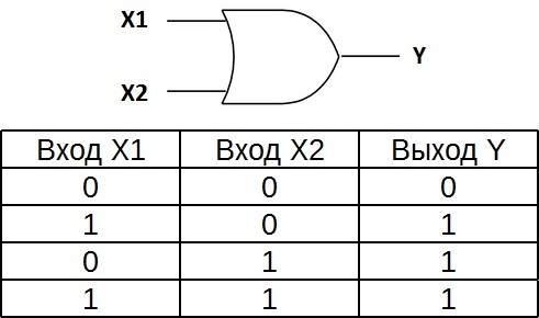
The truth table for the element «2OR» shows that for the appearance of a logical unit at the output, it is sufficient that the logical unit is on the first input OR on the second input. If the logic will be on two inputs at the same time, the output will also be one.
In Western diagrams, the OR element has a rounded entry point and a rounded exit point. On internal diagrams — a rectangle with the symbol «1».
Logic gate «NO» — negation, inverter, NO
«NOT» is a logical element that performs the logical negation operation on the input data. This element, which has one output and only one input, is also called an inverter because it actually inverts (inverts) the input signal. The figure shows the conventional notation of the "NO" logic element.
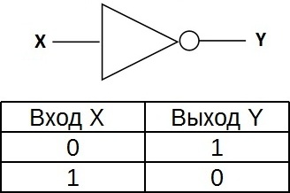
The truth table for the inverter shows that a high potential at the input gives a low potential at the output and vice versa.
In Western diagrams, the icon of the element «NO» has the shape of a triangle with a circle at the exit. On bit chains — a rectangle with the symbol «1», with a circle at the output.
Logical element «AND-NOT» — connection (logical multiplication) with negation, NAND
«AND-NOT» — logical element that performs the operation of logical addition of the input data, and then the operation of logical negation, the result is fed to the output. In other words, it's basically the AND element supplemented with the NOT element. The figure shows the conventional notation of the logic element «2I-NOT».
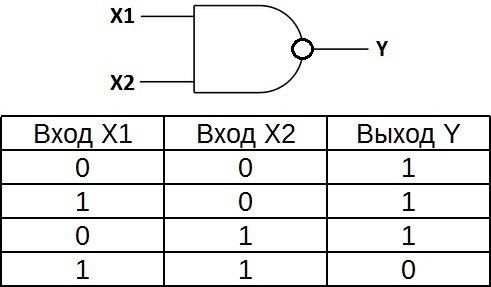
The truth table for the NAND element is the opposite of the truth table for the AND element. Instead of three zeros and a one, there are three ones and a zero. The NAND element is also called a Schaefer element in honor of the mathematician Henry Morris Schaefer, who first noted the importance of this logical operation in 1913. It is designated "And", only with a circle at the exit.
Logical element «OR-NOT» — disjunction (logical addition) with negation, NOR
«OR -NOT» — a logical element that performs the operation of logical addition on the input data, and then the operation of logical negation, the result is fed to the output. In other words, it is an "OR" element supplemented with a "NOT" element — an inverter. The figure shows the conventional notation of the logic element «2OR-NOT».
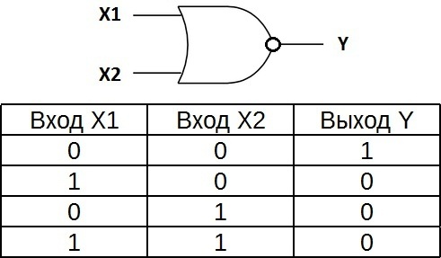
The truth table for the OR-NOT element is the opposite of the truth table for the OR element. A high potential at the output is obtained only in one case — low potentials are applied simultaneously to both inputs. Indicated as «OR», only with an output circle indicating inversion.
Logic gate «exclusive OR» — addition modulo 2, XOR
"Exclusive OR" — a logical element that performs a logical operation of adding input data modulo 2, has two inputs and one output. These elements are often used in control schemes. The figure shows the symbol for this element.
The image in Western schemes — as «OR» with an additional curved bar on the side of the entrance, in domestic ones — as «OR», only instead of «1» will be written «= 1».
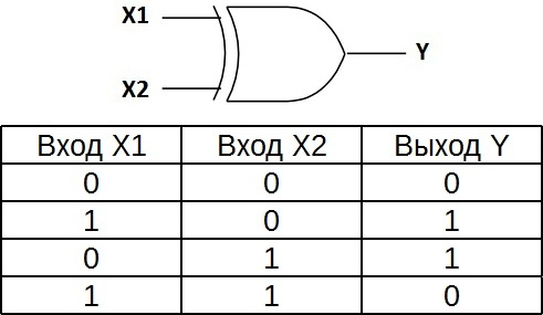
This logical element is also called an "inequality". A high voltage level will be at the output only when the input signals are not equal (one one, another zero, or one zero and the other one), even if there are two ones at the same time at the input, the output will be zero — this is the difference from «OR». These logic elements are widely used in adders.