Functional and structural diagrams of a microprocessor relay device for protection and automation (MP RPA)
The relay protection and automation device (RPA) starts to work and operates depending on the deviation of the parameters from the nominal protected equipment in its elements and the deviation of the nominal parameters from the mode of operation of networks and systems. Parameter information is transmitted by measuring current transformers (CT) or (TA) and voltage (VT) or (TV).
With conclusions current transformers and voltage transformers parameters of the transient process in the electrical system are downloaded, as if by sensors.
The parameters consist of:
-
free aperiodic;
-
periodic, flickering;
-
forced, harmonic — components.
Furthermore, these transient parameters are isolated as low-pass filter (LFF) output signals. These signals are converted in an analog-to-digital converter (ADC) and fed with periodicity in the amplitude frequency response (AFC) to a digital filter.As a result, the transient signal is converted into digital pulse information.
Measurement conversion is carried out on the basis of input information signals for relay protection and automation, as well as on the basis of software decomposition of symmetrical components of the direct, negative and zero sequence of transient currents and voltages.
When the information received exceeds certain settings logic gates give a pulse of permission to disconnect the protected object from the RPA executive block acting on the circuit breaker drive (Q) (see — The main types of relay protection and automation)
Microprocessor based protection and automation devices
The MPRZA (Microprocessor Based Protection and Automation Device) consists of:
-
measuring part (IC), which controls the values of currents and voltages and determines the state of operation or non-operation;
-
logic part (LG), which generates a logic signal depending on the operation of the IC and other requirements;
-
control (executive) part (UCH), designed to amplify and multiply the logic signal received from the LP and the supply voltage for turning off the object and a signal for the operation of the relay protection;
-
power supply (IP) for supplying operating power to all elements of the relay protection.
See on this topic:Advantages and disadvantages of microprocessor protection of electrical equipment
Functional scheme of relay protection and automation of MR

Functional diagram of relay protection and automation
In microprocessor-based relay protection and automation devices (MR relay protection and automation devices), as well as digital relay protection and automation devices, operating and logic microcircuits, microcontrollers, microchips are used and assembled into functional terminals.
An element-based block diagram, for example, might consist of:
-
TA (TV) — current or voltage transformers, with the help of which primary values are converted into secondary, «safe» for further use;
-
ADC - analog-to-digital converter, which allows the conversion of analog values of currents and voltages into digital (binary or hexadecimal) values suitable for processing by a microprocessor program;
-
microprocessor — a complex integrated microcircuit that allows you to receive, record and perform actions on signals; microcircuit with recorded microprogram;
-
DAC-digital-analog converter;
-
IO — executive — usually a discrete output whose state changes when scripts are executed.
Block diagram of microprocessor relay protection and automation of MR
Figure 6 shows a block diagram of a microprocessor-based relay protection and automation device (MP RPA).
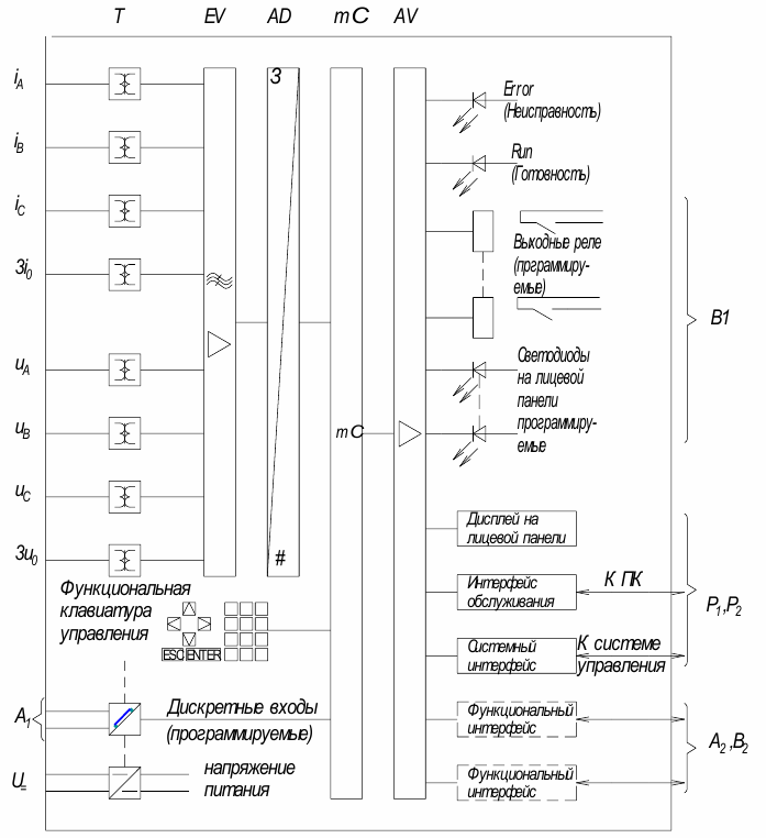
AC analog input values in the general case (iA, iB, iC, 3I0, uA, uB, uC, 3U0) are phase quantities and zero sequence values of currents and voltages. These values are fed through intermediate current and voltage (T) transformers shown in the diagram.
The analog input units must provide sufficient insulation strength of the measuring circuits against the secondary circuits of the high-voltage current and voltage transformers.
The following blocks:
-
EV — converters providing analog filtering and normalization of input signals;
-
AD-analog-to-digital converters for producing digital values.
The main element of the device is a microprocessor unit. It is intended for:
-
filtration and primary processing of measured values;
-
continuous control of the reliability of the measured values;
-
checking boundary conditions;
-
signal processing of logical functions;
-
generation of commands to turn off / on and for signals;
-
registration of current and emergency events, registration of instant damage data;
-
ensuring the functioning of the operating system, eg data storage, real-time clock, switching, interfaces, etc.
Discrete input values (A1):
-
signals about the status of the elements of the power system (keys, etc.);
-
signals from other relay protection devices;
-
signals to enable or disable certain security features;
-
control signals that change the protection logic. They are designed to input logical (0/1) information.
AV block — output amplifiers that provide output relays, signal elements (LEDs), front panel display and various interfaces, which will be discussed below.
Discrete outputs (output relays B1 and LEDs) are used for control and signaling purposes as indicated in the block diagram.
The display is intended for reading security messages and for performing operations using the keyboard.
The system interface provides communication between the protection and the monitoring and control system to transmit various protection status messages, management and data backup. Through this interface, signals for changing the protection parameters can also be transmitted.
The functional interface provides a quick exchange of information with other protections, as well as for the transfer of information to the supervisory control system.
The functional front panel control keyboard is designed to enter control information:
-
change settings and security parameters;
-
input (output) of individual protection functions;
-
entering commands to control the switching elements of the bay;
-
programming of discrete inputs and outputs;
-
Carrying out control checks of the device's serviceability.
See also:Protection and automation terminals based on ABB microprocessors