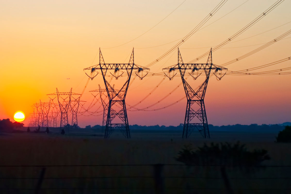
Metal poles of overhead power lines (PTL)
The field of application of metal supports of overhead power lines (PTL) is mainly determined by a number of significant advantages that favorably distinguish supports made of metal from supports made of wood and reinforced concrete.
The advantages of metal supports compared to wooden ones are as follows:
-
Longer service life;
-
The ability to withstand fire and destruction from lightning discharges in the support;
-
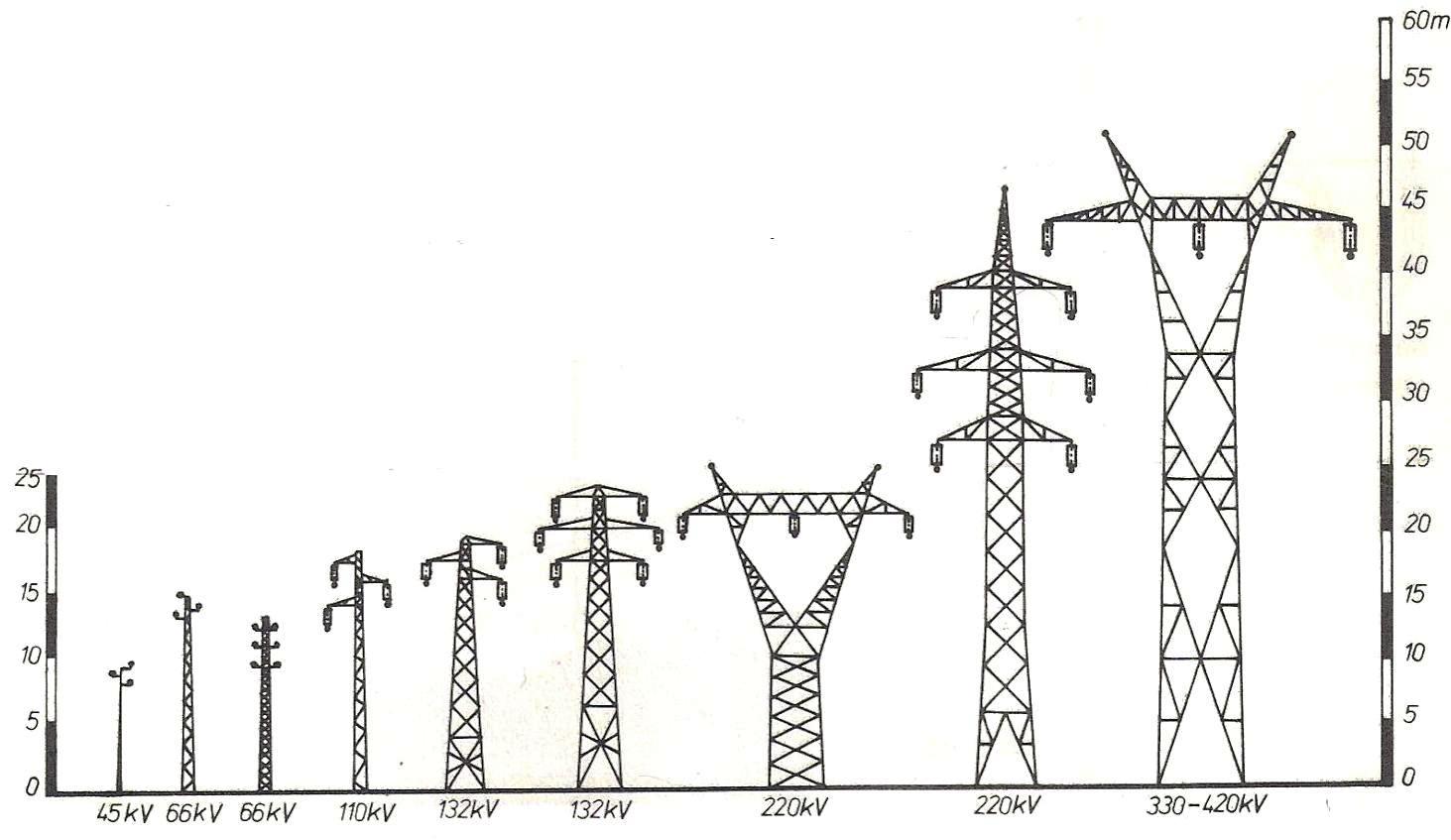
Support for significantly more cables and virtually unlimited support heights;
-
High operational reliability and ease of maintenance;
-
The best conditions for grounding and hanging protective cables;
-
The best architectural design of the pylon;
-
Large assembly, allowing the production of entire main support elements or individual sections in factories, which significantly reduces labor-intensive work on the track. In addition, metal supports with the same loads and height are approximately lighter than wooden and reinforced concrete ones.
The disadvantages of metal supports are:
-
The need for their periodic painting to prevent rusting;
-
Poor use of vehicle capacity when transporting props;
-
The need to carry out special work on the track (installation, drilling and sometimes welding of metal structures), which requires a skilled workforce of various specialties and complicates the installation;
-
Increased initial line construction costs.
Metal supports are made:
-
on lines where high operational reliability, long operational life of the support is required, as well as with double chain lines;
-
at large crossings through various engineering structures or through rivers;
-
in urban and industrial areas and in mountainous areas where wooden supports are not placed due to their large plan dimensions.
Structural elements of metal supports
The metal support consists of the following four main structural elements:
-
foundation;
-
support of a main column or shaft;
-
traverse;
-
ropes or support horns.
The base of the foot serves to anchor it in the pound and provides stability to the foot. In some cases, the bases of the supports are made of metal.
The main column, as a support for fastening sleepers and ropes at a certain height from the ground, perceives all external loads from wires and cables and transfers them to the base.
By design, the main column or support shaft is a lightweight lattice space truss with a rectangular or square cross-section. In almost all types of supports, the cross-sectional dimensions of the support column decrease from bottom to top.
The spatial truss, which serves as a support rack, consists of:
-
four main bars (ribs), called chords, which carry most of the load;
-
systems of auxiliary bars or grids located on the four sides of the support and connecting the belts;
-
several systems of horizontal brackets located in separate cross-sections of the support and called diaphragms.
The joints of the lattice bars with the belt or with each other are called nodes. The center of a node is the point of intersection of the longitudinal axes of the bars converging at a given node.
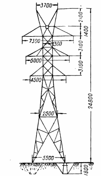
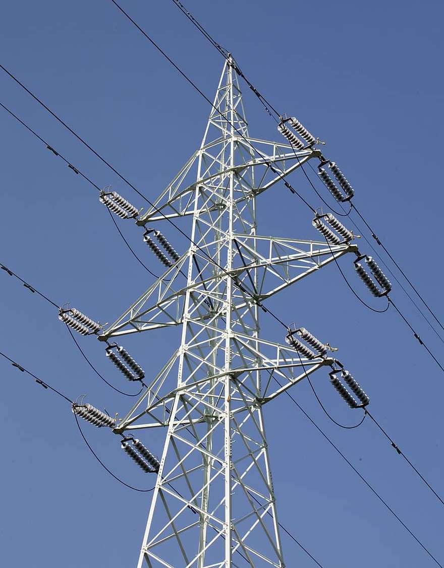
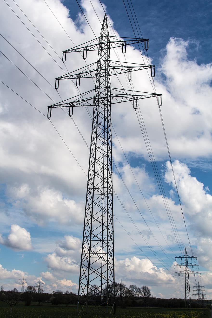
Metal intermediate two-chain support
The part of the chord located between two adjacent nodes is called a panel, and the distance between the centers of these nodes is the length of the panel.
The lattices and granites of the columns are distinguished by their position relative to the axis of the line.
The transverse or front faces (lattices) are the support faces located across the axis of the line, and the longitudinal or lateral faces are the faces parallel to the axis of the line.
Often the grids on two sides of a column or even on all four have the same configuration (diagram).
Support sleepers are designed to fasten wires to the support using insulators with reinforcement at a certain distance between them and from the support shaft.
In most 35 and 110 kV sleeper constructions sleepers are made of corners in the form of small triangular cantilever structures attached to the supporting shaft. Less often, the traverses are made of channels. Trusses are often in the form of long spatial trusses with a square or rectangular cross-section.
Rope resistant or horns are used to fasten protective cables at a certain distance above the conductors. They are made in the form of light structures that form the upper part of the support.
Spatial trusses, which form the main parts of the supports, differ from conventional construction metal trusses:
-
the lightness of the axes of the structure, consisting of rods made almost exclusively of single angles, often small and medium profiles;
-
increased by 1.5 — 2 times the flexibility of both individual rods and the entire truss as a whole;
-
significant transverse dimensions of the truss and its great height.
Due to the noted characteristics, the metal structures of the supports of overhead power lines have a low volumetric weight, which creates a low coefficient of utilization of the load carrying capacity of vehicles during transportation. In addition, the presence of small corners in the structure, with an increased flexibility factor, creates significant difficulties in preserving them from damage during loading, unloading and transportation.
In the process of production and installation of metal supports, the method of connecting the rods is of no less production importance than the type of construction. The following band connections apply to both factory and metal support assemblies:
-
riveting;
-
welding;
-
bolted connections.
The connection method is selected in the technical design, and during the detailed design of the supports, the corresponding node designs are developed. This circumstance should be taken into account by the construction industry and the question of the connection method most suitable for the construction conditions of this line should be resolved in a timely manner.
Previously, riveted joints were one of the main methods of connecting rods in supports, and now, due to production reasons, they are completely replaced by welding or bolts, not only during installation, but even at the factory.
Welding is one of the common methods of connecting rods in the construction of metal supports. The low cost of welding in the factory, a significant simplification of the production process of welded structures and a certain reduction in their weight determine the wide use of this method of joining, which has significant advantages over others.
In the production of metal supports, the connection of the rods is almost exclusively carried out by electric arc welding. Significant difficulties with the supply of the line of picket welding units, the cost of liquid fuel and the maintenance of the device by qualified personnel, as well as the need to rotate when welding structures, limit the possibility of using welding in the installation.
Bolted connections are used in the installation of supports on lines due to difficulties in the production of rivets and electric welding of pads.
The use of bolted joints in support assemblies is due to a number of the following advantages over riveting and welding:
-
great simplification of the process of installing supports, which does not require tilting structures, special tools, equipment or mechanisms;
-
the ability to make bolted connections without the use of skilled labor (rivets or welders);
-
significantly reducing the time spent on assembling the supports.
Disadvantages of black bolt connections include:
-
a certain reduction in the reliability of a bolted joint versus welded or riveted, due to the uneven distribution of forces between the bolts;
-
significant costs for hardware (bolts, nuts and washers), the number and sizes of which are greater than for rivets of equal strength.