Indirect electrical controllers
 Electric and electronic controllers use electrical energy to control the drive.
To create positional automatic control systems in foundries and thermal workshops, serial devices of various modifications equipped with electrical contact devices are used. Relay transducers (bimetallic, dilatometric, etc.) can be used for positional control.
Temperature control circuit on-off
In the scheme for two-position temperature regulation in the drying oven (Fig. 1), the heating system of the drying oven is arranged in such a way that if the temperature in the working space becomes lower than the permissible one, then the heating elements EK1 must be switched on at high power, and if temperature becomes higher than the permissible, then the EK2 elements with low power.
A resistance thermometer 1 is used as a sensitive element connected to an electronic bridge 2 in a three-wire circuit.If the temperature in the furnace deviates from the set value, then the electrical resistance of the thermometer will change and an imbalance signal will appear in the diagonal of the bridge.
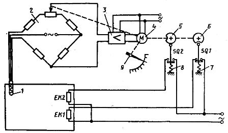
Rice. 1. Diagram of a two-position electric temperature regulator
The signal amplified by the electronic amplifier 3 drives the rotation of the reversing motor 4. The direction of its rotation depends on the sign of the imbalance, that is, on the sign of the temperature deviation from the set value. Two disks are kinematically connected to the rotor of the electric motor: 5 and b, the position of which depends on the angle of rotation of the rotor, therefore, on the position of the sliding wire and the arrow 9 of the bridge.
The guides of the contacts SQ1 and SQ2 are pressed against the disks by means of springs 7 and 8. When the disks rotate, the contact SQ2 is closed in the interval of the instrument readings from the beginning of the scale to the valley of the disk 5 and is open in the interval from the valley to the maximum of the rock. Contact SQ1, on the contrary, is open from the beginning of the scale to the valley of disk 6 and is closed in the interval from the valley to the maximum of the scale.
When the lower temperature limit is reached, the contact SQ1 closes and the high power heating elements EK1 are switched on. When the upper temperature limit is reached, contact SQ2 closes and contact SQ1 opens, causing the temperature to slowly decrease. As soon as the lower temperature limit is reached, the situation will repeat itself, and so on.
In fig. 2 shows a circuit diagram of two-position temperature regulation in the working space of a chamber furnace type SNZ-4,0.8,0.2,6 / 10 with a protective atmosphere. The oven is three-phase and connected to the oven via FU fuses.The heating elements are switched on and off using a contactor. Temperature stabilization is provided by an automatic control system (ACS).
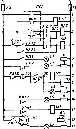
Rice. 2. Electric circuit for regulating the temperature of the working space of a chamber electric furnace with a protective atmosphere
The control circuit consists of 13 circuits. Based on their functional characteristics, they can be divided into control circuits, protection circuits and information circuits. The control is carried out by: the temperature in the working space of the furnace (automatic and manual in case of failure of the automatic control system), the supply of a protective atmosphere to the furnace, the supply of a gas curtain. Information schemes are used to warn the operating personnel about the different operating modes of the furnace by means of light and sound signals.
The oven has one zone. Temperature regulation is carried out using an automatic control system consisting of a thermocouple, compensation wires, potentiometer PSR, intermediate relays KA1 and KA2, contactor KM and finally the oven itself SNZ-4,0.8,2.6 / 10 .The PSR potentiometer is connected to the control circuit using circuits 1, 2 and 3. Circuit 1 serves to power the PSR device itself.
Circuits 2 and 3 contain the minimum (min.) and normal (normal) contacts of the PSR thermostat. The maximum contact (max) of the PSR is not used in the circuit. In circuits 2 and 3, a control signal is generated, which, with the help of intermediate relays KA1 and KA2, is amplified to the value required to actuate the drive coil (KM contactor). Thus, KA1 and KA2 act as power signal amplifiers.
Circuits 3 and 4 have universal three-position toggle contacts: auto (A), off (O), and manual (P). Each of these positions corresponds to a certain mode of operation of the furnace: automatic control of the temperature in the furnace, the furnace is turned off, manual temperature control (only when adjusting the modes or in case of failure of the automatic control system).
Circuit 4 includes the contactor and therefore the heaters themselves. The contactor can only be switched on if the oven door is closed. The latter is provided by the introduction in circuit 4 of the limit switch SQ1, which is turned off when the oven door is opened. Direct switching on of the contactor coil and, accordingly, its contacts is carried out as follows: with automatic control — through contacts of intermediate relays KA1 and KA2, with manual control — only using contacts KA2.1.
Coil KA1 is switched on only when the temperature in the furnace reaches a minimum value. Coil KA2 is connected to the contact corresponding to the normal temperature in the oven. Therefore, the furnace heating elements remain on even when the furnace temperature becomes equal to the set point. The heaters are disconnected from the mains only when the temperature in the oven rises above the norm. This is how the circuits that control the stabilization of the temperature in the oven are composed.
Whether the oven is on or off at the moment, we are informed by two signal lamps: L1 and L2. When the heating elements are on, the L1 signal lamp is on, and when the heaters are off, the L2 lamp is on. This is achieved by connecting the contacts of the contactor KM in circuits 5 and b.Resistors R in circuits 5 and 5 are needed to lower the voltage in the signal lamps from 220 V to the operating voltage (the resistors in the lamp circuits play the role of load resistors). Circuits 7, 8 and 11 are designed to control the supply of protective atmosphere and gas curtain.
The circuit contains solenoid valves M1 and M2 respectively for supply of protective atmosphere and supply of gas to create a gas curtain in the furnace.
As can be seen from the structure of circuit 7, it is possible to supply a protective atmosphere to the furnace only if the temperature in the furnace has not dropped to a minimum (when KA1 is turned on, circuit 7 opens through contact KA1. 2). This system is an explosion protection system. Gas supply to the furnace is controlled manually using buttons SB1 and SB2. The KAZ relay is introduced to multiply contacts, since M1 does not have blocking contacts.
When M1 (as well as KAZ) is turned on, the signal lamp L3 lights up at the same time, notifying the service personnel that the gas valve is open. Turning off the gas (using the SB1 button) is accompanied by turning off and L3, while another signal lamp turns on — L4, which informs that the valve is closed.
Circuits 12 and 13 are informational. Using the package switch SA2, you can turn on the siren, notifying the service personnel that the temperature in the furnace has dropped to the minimum value, which is a sign of some kind of malfunction (the heaters should have turned on even at normal temperature).
Thus, the minimum contact min PSR is used in an evil scheme not only as a temperature stabilization sensor in the working space of the furnace, but also as a sensor in the automatic warning and protection system.The automatic warning system can be turned off by moving the switch to the second position (circuit 13). The L5 lamp signals that the automatic warning system is disabled.
Three-position temperature control circuit
In a three-position regulator, the regulator has a third position, in which, when the value of the controlled variable is equal to the given one, the object is supplied with such an amount of energy and matter as is necessary for its normal operation.
The three-position control circuit can be obtained by some conversion of the considered two-position control circuit (see Fig. 1), if three intermediate relays are controlled using the contacts SQ1 and SQ2. When contact SQ1 is closed, relay K1 turns on; when SQ2 is closed, relay K2 is activated. If both contacts SQ1 and SQ2 are open, then the short circuit relay is activated. With the help of these three relays, the heating elements can be switched on with delta, star or switched off, that is, to perform three-position temperature control.
To create automatic control systems that apply a proportional control law, a balanced relay of the BR-3 type is often used. This relay uses two sliding wires. The value of the controlled variable determines the position of the slide of one slide (sensor), and the degree of opening of the regulating body — the position of the slide of the actuator slide (feedback).
The task of the balanced relay is to have such an effect on the drive that the slider positions of the two sliders would be symmetrical.
In the scheme of the balanced relay BR-3 (Fig.3) the main elements are the polarized relay RP-5 and the output relays BP1 and BP2. While the positions of the slides are symmetrical, the strengths of the current flowing in the two coils of the polarized relay are equal and therefore its contacts are open. Output relays BP1 and BP2 are de-energized and their executive contacts are open.
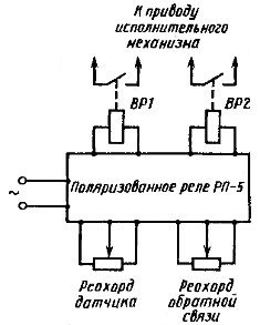
Rice. 3. Simplified block diagram of a balanced relay type BR-3
In case of a deviation of the controlled value (for example, when increasing), the position of the slider of the sensor slider is changed. As a result, the symmetry of the bridge and the balance of the current flowing through the windings of the polarized relay are disturbed and the corresponding contact is closed. In this case, the output relay is activated, the contacts of which include the drive, which moves the regulating body in the direction of decreasing the controlled value. The feedback slider slider moves at the same time.
The drive operates until the slider of the feedback slide wire occupies the position of the sensor slide wheel, after which equilibrium again occurs. The relay contacts open and the drive stops. This provides a constant relationship between the value of the controlled variable and the position of the controller.
To create automatic control systems that apply I-, PI- and other laws, various electronic controllers are used, which include regulators of the type IRM-240, VRT-2, EPP-17, etc.