Classification of control systems according to the algorithm of operation
 The value of the controlled variable and the nature of its change, as we have already seen, depend on a number of factors: the influence of the setting, time, disturbing influence, etc. these factors.
Any automatic system is determined by the nature of its functioning algorithm (the law of reproduction), the nature of its control algorithm, and the presence (absence) of the ability to self-adapt. These characters are the basis of the classification of automatic systems.
By the nature of the functioning algorithm, automatic systems are divided into stabilizing, tracking and software.
V stabilizing systems adjustable value y for any disturbances F (f) acting on the system, the controller is kept constant and equal to the given value yo within the tolerances y = yo + Δy,
where Δy — deviation of the controlled value depending on the magnitude of the disturbance F (t) acting on the system.
The tuning actions x (t) in such systems are constant, predetermined values: x (t) = const.
Automatic stabilization systems can be implemented on the principle of astatic and static regulation. For more details see here: Astatic and static regulation.
YES tracking systems Automatic control systems include systems in which the reproduction of an input value varying according to an arbitrary law is carried out at the output of the system with an acceptable error.
The reproduction law for a tracking system can be written in the following form: y = x or y = kx,
where x is an arbitrary input quantity that depends on time or other parameters and is usually unknown in advance, k is a scale factor.
In servo systems, a terminology is used that is different from the terminology used in control systems: instead of «regulation» they say «tracking», «end of process» — «working out», «input value» — «leading value», «output value» — «subordinate value».
In fig. 1a shows an exemplary block diagram of a servo system.
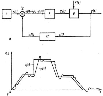
Rice. 1. Block diagram (a) and diagram (b) of the changes in the angular displacement of the input and output of the servo system: 3 — drive element, D — misalignment sensor, P — controller, O — object, MT — measurement and conversion element.
The main element of the tracking system is the discrepancy sensor D, which determines the discrepancy (error) between the slave and master values. The slave value y is measured by the measuring-converting element of the MF and brought to the level of the master value x.
The discrepancy sensor D sets the value of the discrepancy between the master value x coming from the master element 3 and the slave value y and sends a signal to the controller P, which generates a regulating action Z (t) on the object. The regulator seeks to reduce the resulting mismatch to zero. A deviation of the slave value from the set point of the master follows.
In fig. 1, b shows an approximate diagram of the change in the master x and slave y values of the tracking system.
Automatic systems that make the controlled variable y according to a certain, predetermined law are called software control systems.
The law of reproduction of a software system can be expressed by the equation
y = x (T),
where x (T) is a set (pre-known) time function that the system must reproduce.
In such systems, it is necessary to have a special device — a detector to change the value of the setting x (t) according to a certain required law.
By the nature of the control algorithm, automatic systems are divided into automatic systems with an open loop of action (open control loop) and automatic systems with a closed loop of action (closed control loop).
Auto-adaptive systems are divided into self-adaptive or self-adjusting systems and non-self-adjusting systems. It should be noted that self-adaptive systems represent a new type of system and not all concepts of this type of system are fully formed, therefore in different textbooks they have different names,
All manufacturing plants must operate optimally in terms of energy consumption, productivity and quality of the manufacturing operation.
When automating such plants, it is necessary to have special devices that could provide automatic regulation of the production plant to work in an optimal mode. Such special devices are called automatic adjustment systems, or self-adjusting control systems.
These systems automatically adapt the production unit to changing operating conditions, i.e. to the changing characteristics of the managed object (changes in disturbances), and make it work in an optimal mode; therefore, automatic tuning systems are often called optimal, or extreme, control systems.
The use of such systems makes it possible to increase the productivity of the plant, improve the quality of products, reduce labor costs per unit of production, etc. In the future, many automated installations will have automatic setup systems.