Classification and basic parameters of measuring devices of main and software devices
 Any automatic control system for measuring the deviation of the controlled value from the steady-state value has a measuring body that can not only measure the magnitude and sign of the deviation, but also convert this deviation into a form convenient for further use in the system for automatic control.
The physical nature of the regulated quantities is very diverse, therefore the measuring organs are also diverse. In most cases, however, the output of the measuring device will be either a mechanical quantity (displacement, force) or an electrical quantity (voltage, current, electrical resistance, capacitance, inductance, phase shift, etc.).
The following requirements are imposed on measuring devices used in automatic control systems:
-
reliability in operation under all conditions that can be encountered in a controlled technological process,
-
the required sensitivity
-
permissible dimensions and weight,
-
required momentum,
-
low sensitivity to external influences,
-
has no influence on the technological process and on the measured value,
-
unequivocal indications,
-
stability over time,
-
matching input and output signals with other signals automation elements.

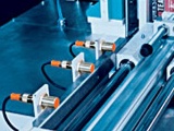
Electrical quantities are the easiest to measure, therefore, in many cases, when measuring non-electrical quantities, a special device (transducer) is carried out together with the measuring body, which converts the non-electrical quantity at the input of the measuring body into an electrical quantity at its output. Such measuring devices are called sensors.
As a rule, no distinction is made between the concepts of a measuring element, a sensor and a sensitive element (the last name is also often found in the literature on automatic control).

The most common are electrical sensors, that is, measuring devices with the conversion of a measured non-electric quantity into an electrical one. The construction of these sensors depends on the physical nature of the measured quantity and the principle adopted to measure its deviation.
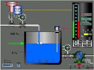
The classification of measuring devices is carried out according to the name of the value they measure: measuring devices for level, pressure, temperature, speed, voltage, current, flow rate, illumination, humidity, etc.
Sensors are classified: firstly, by the name of the measured value and, secondly, by the parameter in which the signals of the measuring device are converted, for example, capacitive level sensors, inductive pressure sensors, rheostat temperature sensors, etc.
For convenience when using the considered classification, as a rule, one of the names is omitted, since the same sensor can be used to measure different non-electric quantities.
Basic parameters of the sensors
The main parameters of the measuring body (sensor) that characterize it are:
-
sensitivity
-
inertia.
Sensor sensitivity is called the change relation Δy controlled variable to change Δx input quantity:
K = Δg /ΔNS
In automatic control systems, this ratio is also called system or link gain (if a link is considered).
Thus, the sensitivity of the measuring element matches its gain.
Inertia of the measuring body (sensor) also determines the possibilities of its application in automation systems, as it causes a certain delay in measuring the value of the controlled parameter at a given time. The delay can be caused by the mass of the parts, thermal inertia, inductance, capacitance and other elements of the sensor itself.
When studying the dynamic properties of an automatic control system, the inertia of the measuring body plays the same role as the inertial properties of any other element of the automation system. Therefore, when choosing a sensor, it is necessary to pay attention not only to its sensitivity, but also to its momentum.