Closed automatic control systems
 Closed automatic control systems (ACS) differ from open circuits in the equipment used and in the completeness of automation. With the ACS open, the main unit (including the control equipment) does not receive information about the actual operating mode of the electrical installation (driving motor, running machine).
In a closed ASUB, information is transmitted to the control elements, which is accompanied by the submission of appropriate command signals. The circuit that transmits such information closes the control loop, forming a closed ACS or feedback ACS.
The difference between closed and open ACS can be explained with the example of controlling the speed of an electric motor in a generator-motor (G-D) system. With the ACS open (Fig. 1, a), the set speed of the electric motor is set manually by potentiometer P. The speed adjustment is carried out visually by a tachometer, which is powered by the TG tachogenerator. Any speed deviation from the set point is eliminated by the operator by acting on the potentiometer slider.
In a closed ACS (Fig.1, b) the armature of the TG tachogenerator is included in the excitation circuit of the OVG generator, creating a closed or feedback system (in this case with speed feedback).
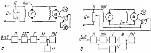
Rice. 1. Electric motor control circuit in the G -M system: a — open ACS, b — closed ACS
The current generated by the tachogenerator (Aztg) in a closed circuit directed to the current of the potentiometer (Azn) and the resulting current acts in the circuit equal to the geometric difference of these currents. Using the slider of the potentiometer, the operator sets the value of the resulting current in the excitation coil of the OVG, at which the corresponding speed of the electric motor is provided. This is where the operator's role ends. In the future, the system automatically maintains the set mode of operation of the electric drive with a certain accuracy.
Suppose that as a result of the load spike, the speed of the electric motor has decreased compared to the specified one. The reduction in speed is accompanied by a corresponding reduction in the speed of the tachogenerator and the voltage at its terminals. This, in turn, will lead to a decrease in the current Aztg in the feedback circuit, and in a certain position of the slider of the potentiometer - an increase in the resulting current in the excitation winding of the generator. The generator voltage and motor speed will increase accordingly.
The process of increasing speed and voltage will continue until the current in the feedback loop reaches the set value and the motor speed reaches the set value.
In the analysis of automatic control systems, function charts… In fig.2 transmissions functional scheme of ACS, which includes the following elements:
1 — main device that sets the mode of operation, gives a command, start pulse or signal,
2 — element of comparison. It includes the signal X1 from the master, the signal X0, which determines the speed or level of the controlled value. Taking into account the signal from the ninth main feedback element, element 2 compares the received signals and sends the additionally corrected signal X2,
3 — the transforming element, the signal op transforms it into another form, more convenient for further transmission. For example, the signal X2 is supplied in the form of hydraulic (pneumatic, mechanical) pressure. Element 3 converts it into an electric current. Since this kind of transformation may require additional energy, then element 3 is connected to a PE energy source,
4 — adding element, it receives two signals: X3 and X8 from the correction element (memory element) 8. These signals are summed by element 4 and sent to the next element,
5 — amplifying element, the input signal X1 may be weak and must be amplified for subsequent transmission. This is done through element 5 which is connected to the PE power source,
6 — executive element, executes the received signal (electric motor, electromagnetic relay, servo motor),
7 — adjustable object or working machine.
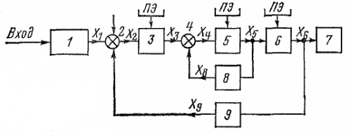
Rice. 2. Functional diagram of ACS
Each automation element is an energy converter, at the input of which the value X' is applied, and the value X is removed from the output. «For each element in a stationary state there is a certain dependence X» (X'), called a static characteristic.
A closed automatic control system is characterized by the presence of feedback; it has at least one feedback loop connecting the output of the system to its input. In addition, there may be so-called internal feedback, connecting the output and input of individual ACS elements.
Feedback is divided into hard and flexible. Hard constraints operate both in transient and stationary modes of operation of the system, flexible — only in transient ones. Differentiate between positive and negative feedback. As the regulated value increases, the positive connection increases it even more, and the negative one, on the contrary, decreases. Feedbacks can transmit signals proportional to angle of rotation, speed, voltage, current, etc. and are called angle, speed, voltage, current feedbacks accordingly. For more details see here: Elements of automation systems
According to the principle of operation, ACS can be divided into three groups:
-
continuous operation in which the relationship between the controlled and set values is not broken,
-
impulse action, in which the connection between the controlled and the set values takes place at regular intervals,
-
relay action where communication only occurs when a value reaches a certain value.
Depending on the law according to which a given value changes over time, ACS can also be divided into three groups:
-
constant or low setpoint systems in which the automatically controlled value is kept constant. These are stabilization systems, which are essentially automatic control systems (ACS),
-
systems in which the target value is changed according to a specific, predetermined program. It is a software management system,
-
systems in which a given value can vary widely and according to an arbitrary law, i.e. tracking systems.