Tuning the PID controller of the frequency converter
The PID control function can be used to control the maintenance of pressure, flow, temperature, etc. A block diagram of a variable frequency drive with PID control is shown in Fig. 1.
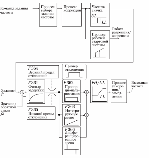
Rice. 1. Block diagram of PID control
PID controller setup
Manufactured in accordance with the requirements of the driven system, the reference signal and the feedback signal. For details on the setting procedure, refer to the operating instructions of the specific frequency converter.
The adjustable parameters for PID control are given in a table. 1.
Table 1. Adjustable parameters of PID control
Name Setting range Delay filter 0 — 255 Proportional factor (P) 0.01 — 100 Integration factor (I) 0.01 — 100 Upper deviation limit 0 — 50 Lower deviation limit 0 — 50 Differentiation coefficient (D) 0 — 2.55
Proportional link setting
The proportional link (P) amplifies the bias (the difference between the reference and feedback signal) to compensate for control proportional to the bias. As its value increases, the response of the control action is accelerated, but an excessive increase in the proportionality factor can cause unstable operation and oscillations (Fig. 2).
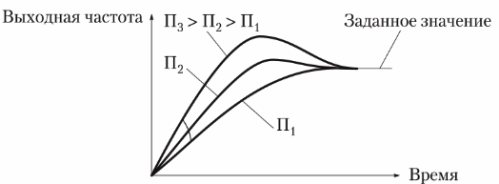
Rice. 2. Setting the proportional band (P-range) of the PID controller
Integrator setup
The integrating relation (I) cancels the residual deviation after the proportional relation. The larger the integration coefficient, the smaller the residual deviation, but an excessive increase can cause unstable operation and oscillation (Fig. 3).
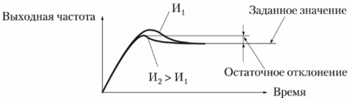
Rice. 3. Setting the integrating element (I-element) of the PID controller
Setting the differentiator
The differentiating link (D) improves the response of the system when the deviations change rapidly. However, increasing the derivation factor too much can cause fluctuations in the output frequency.
Filter setting delay
The delay filter is designed to contain rapidly changing biases (first-order delay relation). If you reduce the delay, the process will speed up and vice versa (Fig. 4).
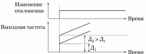
Rice. 4. Setting the delay filter
Setting the feedback signal
Selecting a PID control signal will allow you to specify the source of the feedback signal. When using the analog input, the feedback signal is set to zero corresponding to the frequency of 0 Hz, and the maximum value corresponds to the maximum frequency. For example, if a 4-20 mA signal is used, set 20% for 0 Hz and 100% for maximum frequency.
Setting the work signal
The reference value is used as a frequency set command with the speed reference selection function. The reference frequency value is set as the technology parameter value to which the feedback value will aim. The reference can also be set using preset speeds.