What is a mnemonic diagram, purpose, types, principles of creation, designations on diagrams
For the convenience of visual perception of the functional diagrams of controlled or controlled objects, mnemonic diagrams are used — graphic representations of the diagrams of these objects. A mnemonic diagram can show, for example, a CNC machine shop, a technological process or a system, for example an energy network. In other words, a mnemonic diagram is an informational conditional model of a system or process in the form of symbols that denote parts of the system as well as their relationships.
The mnemonic diagram graphically reflects the structure of the entire system, thereby facilitating the work of the operator, who, thanks to such a scheme, can more easily remember the structure of the system, the relationship of parameters, the purpose of certain controls, tools, metal-cutting machines, etc.
For the operator controlling the processes, the mnemonic diagram serves as perhaps one of the most important sources of information about the processes currently taking place in the system, about the structure and nature of these processes, about the current state of the system, in particular about incidents and violations of normal operating modes.
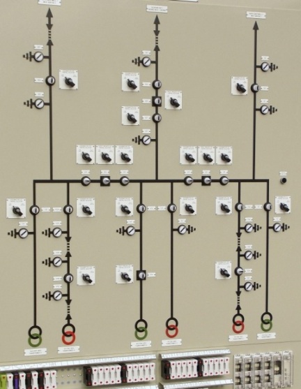
Most often, mnemonic diagrams are based on the use of technological diagrams. A technological scheme is understood as a conditional graphic representation of a set of main and auxiliary elements (equipment) and connections between them, which determines the main technological process.
Schemes are executed in a planar image without observing the scale, do not take into account the actual spatial arrangement of elements or take it into account approximately.
For example, technological diagrams of power plants and networks include: thermal diagram of a power facility (TPP, NPP) or installation (unit, unit, reactor), diagram of a fuel oil facility with steam and oil pipelines, diagram of a chemical complex for water purification, diagram of primary and secondary electrical connections, as well as diagrams of individual assemblies (steam piping, power lines, starting circuit of the power unit, back-up excitation, operational blocking of disconnectors, 6 kV auxiliary supply, protections, etc.).
These diagrams show all available communications, equipment, fittings, elements and parts with the designations adopted in the power plant and the necessary graphical and textual explanations.
If the controlled object has a complex structure, there are many parameters that need to be operationally controlled, and it is a technologically complex scheme.If during the operation of the object the technological scheme itself can change, in these cases mnemonic schemes turn out to be very, very effective tools. They can show the states of individual devices, machines, aggregates, the values of various parameters, and also provide general information about the progress of the technological process.
An operator working in conditions of an abundance of information coming to him, thanks to mnemonic diagrams, can more efficiently carry out information retrieval, since a mnemonic diagram always implies logic, it shows real relationships between the parameters of an object that needs to be control or monitor .
With the help of a mnemonic diagram, the operator can easily systematize logically and promptly process the information that comes to him, technical diagnostics in case of deviation from the norm is also facilitated. Therefore, the mnemonic scheme serves as an external support for making the best decision and applying the correct control action.

Mnemonic diagrams are always created adhering to a number of principles formed over many years of practical application of mnemonic diagrams. And one of the main principles is brevity. The mnemonic diagram should not contain anything superfluous, it should be as simple as possible. In the absence of ambiguous elements, the displayed data should be displayed clearly and concretely, as briefly as possible, so that they can be easily perceived and further processed in a timely manner.
The principle of unification (summarization) implies the selection of the mnemonic diagram and the use in it of the most significant features of the objects, that is, it is not necessary to show insignificant structural features of the system on the mnemonic diagram. Symbols of similar processes and objects should be combined and unified.
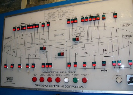
The principle of accentuating controls and controls dictates the need, first of all, to emphasize with shape, color and size the most important elements serving to control the state and prompting important decisions to be made regarding the impact on the object of control.
According to the principle of autonomy, it is important to separate from each other the parts of the mnemonic diagram corresponding to the autonomously managed and controlled units and objects of the system. Individual parts are clearly distinguished from others, obeying the principle of structure, according to which they must have a structure that is different from other structures and easy to remember, while the structure must adequately reflect the nature and basic properties of the object on mnemonic diagram.
The principle of spatial correspondence of control and control elements obliges to place indicators and instruments strictly in accordance with the location of the corresponding control elements, so that the law of compatibility of the reaction with the stimulus is observed.
One of the key principles in creating mnemonic diagrams is the principle of using stereotypes and familiar associations.The operator must associate the parameter conventions with the standard designations of these parameters, which are generally accepted, and instead of abstract icons, it is better to use symbols that precisely denote the relevant processes and objects.
The figure shows an example of different designations for the same parameters. Here, letter designations are shown in the top row, their conventional designations in the second row, and mnemonic symbols in the third row. Obviously, mnemonic symbols are similar in outline to letter outlines, therefore mnemonic symbols are preferred.
Practice shows that the use of mnemonic symbols leads to a reduction in the number of errors and a reduction in the time the operator spends on character recognition by 40%.
However, the mnemonic diagram should not completely copy the technical structure. Its task is to show the logic of the controlled and monitored processes, simplify the search and identification of the necessary information for the operator, help to quickly make the right decision and perform the necessary operation on time.
The mnemonic diagrams are dispatcher and operator. Operator rooms show one technological complex, and control rooms - a scattered system consisting of objects, complexes, aggregates, etc. objects.
If the operator performs a switch directly on the mnemonic diagram, then such an operator mnemonic diagram is called operational. If the mnemonic diagram serves only to inform the operator, it is a non-working mnemonic diagram. Sending mnemonic diagrams are similarly subdivided into mimic and light.
The operational mnemonic diagram, in addition to display devices and gauges, signaling and pictorial elements, also includes controls for a caller or individual type. On the mimic dispatcher mnemonic diagrams there are switches for manually removing signals and obtaining data on the mimic diagram for the current real state of the controlled object.
If on the mnemonic diagram each of the information elements is associated with a separate sensor, such a mnemonic diagram is called a single object or separate. If it is possible to switch between several objects of the same type, then such a mnemonic scheme is called multi-object or selective (calling).
So calling mnemonic diagrams can switch between multiple sensors on a single object or between objects. Calling mnemonic diagrams allows you to reduce the area of \u200b\u200bthe panel, instead of several use one, save on the installation of devices and information processing systems, as well as facilitate the operator's work by simplifying the circuit and narrowing the field of view.

If a mnemonic diagram always shows a constant diagram of the same object, then such a mnemonic diagram is called a constant. If depending on the operating modes of the object, depending on the nature of the ongoing processes, the image changes significantly, such a mnemonic scheme is called replaceable. For example, the initial scheme is displayed first, then the scheme for normal operation of the object, and in the event of an emergency, the emergency scheme.
Mnemonic charts are found both on the console panel and on individual panels, on console attachments, and on dashboard add-ons.The information display can be presented in both discrete and analog form, or in analog-discrete form.
According to the shape of the symbols of the unit, object, technological equipment, mnemonic diagrams are divided into volume, flat and relief. According to the coding method — in symbolic and conditional. Symbols are in no way related to real processes and objects. In the above figure, the second row corresponds to the conditional encoding method, the third to the symbolic one.
In the way that symbols or signs appear on mnemonic diagrams, images can be of direct or inverse contrast. The elements are applied by photographic method, drawing, sticker, electroluminescent light sources, gas discharge, LED, incandescent lamps, CRT and other displays.
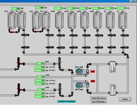
Displays are now the most popular, because with a complex branched structure of an object, when technologically regularly the process changes and in fact several mnemonic chains are needed. The display screen allows you to display a mnemonic diagram of the entire system or diagrams of individual objects or nodes. Calling up the necessary mnemonic scheme on the screen is done by the operator himself or the computer.
During the development of mnemonic schemes, the most optimal form of symbols is selected. At the same time, they must be closed, and additional lines and elements must not intersect with the outlines of the symbol, so as not to interfere with the reading of information by the operator. The requirements are particularly high for alarm symbols and for symbols indicating functional status.
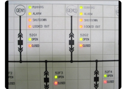
Green is usually used to indicate «enabled» and red is used to indicate «disabled».A new state interrupt signal informs about a change in state, for example, if the device was initially working and the indicator was green, then when it was turned off, a red intermittent flash. The flash frequency is from 3 to 8 Hz, with a flash duration of at least 50 ms. The status change alert can only be disabled by the dispatcher himself.

As for the connecting lines of the mnemonic diagram, they should be solid straight lines, as short as possible and have as few intersections as possible. If the mnemonic diagram is very large, many objects are represented on it, while the colors are different and bright, the operator's vision is overloaded. For this reason, mnemonic diagrams always try to reduce the number of colors that overwhelm the eyes: purple, violet and red. The background color should not be saturated and it is better if its color is light yellow, light gray or light green.
When evaluating ready-made mnemonic diagrams, the ratio between the number of passive and active elements is taken into account, this indicates the degree of information content of the mnemonic diagram, the ratio of the number of passive elements to the total number of mnemonic elements is also calculated.
In principle, when designing a mnemonic scheme, several of its final variants are considered, and by modeling the mnemonic scheme in one way or another, the process of the operator's interaction with the mnemonic scheme is also simulated. The faster the operator is able to solve the set tasks and the fewer mistakes he makes, the more successful the mnemonic scheme is considered.
The scope of application of mnemonic diagrams today is enormous.Mnemonic circuits are widely used in construction, metallurgy, energy, mechanical engineering, instrument making, railways and the transport industry in general, as well as in many other industrial and civil sectors.