Fiber optic sensors in industrial automation systems
Determining the presence of a part of the conveyor on an automated line, obtaining information about the operation of a lighting device, managing a compact but efficient machine .. Everywhere a minimum of errors is required in the control of the process, and if a failure occurs, it is important to know the cause of the malfunction, so that mistakes are not repeated in the future, because modern technological processes do not tolerate poor quality. This is where sensors come to the rescue.
There are many types of sensors: magnetic, inductive, photoelectric, capacitive — each of them has its own advantages and disadvantages. Photovoltaic is one of the most versatile. Here are laser and infrared, single beam and reflective. But we will look at optical sensors, since they have the widest configuration options and are ideal even for the most difficult-to-reach places.
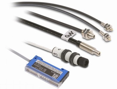
The optical optical sensor is divided into a pair of devices: an optical photovoltaic amplifier and an optical cable with an optical head. The cable passes light from the amplifier.
The principle is simple.Emitter and receiver work together: the receiver detects the light wave emitted by the emitter. Technologically, this process is carried out in different ways: tracking the angle of a light wave, measuring the amount of light, or measuring the return time of a light wave in order to measure the distance to an object.
The optical source and receiver can be located simply in the head (diffuse or reflective units), or they can be made separately — two heads (single beams). The fiber optic sensor head contains the electronics inside, while the receiver is connected to the electronics right through an optical fiber. The received and transmitted waves travel through the fiber in a manner similar to high-speed data transmission in optical networks.
The advantage of this separation is that the receiver is installed on the measured object. Fiber optic cable is routed and connected to the amplifier, which is housed in a special control cabinet that protects the amplifier from the often harsh outdoor environment of the manufacturing plant. The choice of options is varied. Amplifiers are simple and complex, in particular multi-functional, with the ability to perform logic and switching operations.
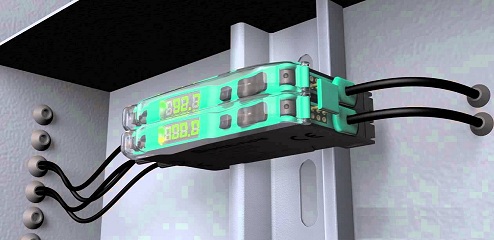
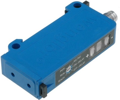
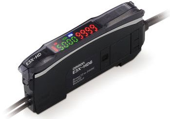
The basic set of fiber-optic sense amplifiers have a minimum of electronic components and functionality, and the most sophisticated ones are plug-and-play, with the electronics being completely customized. Some sensor electronics are capable of handling more than 10 input fibers. Of course, there is also an indication. The indicators show whether the sensor is working properly. It also has other features.
The interface for the controller is determined by the output format.Both sensor setup and amplifier reset are provided here. Outputs are normally open, normally closed, collector, emitter, push. Connections are made with a multi-core cable. Programming is done using buttons or simply a potentiometer.
Additional flexibility is provided by such sensor options as: on / off delay, pulse outputs, elimination of intermittent signals, — to achieve greater freedom in detailing and adjusting the amplifier parameters depending on the individual requirements of the production process. Delays allow you to delay the reaction of the working body, interrupting signals serve as a sign that the working conditions are violated. Everything is personalized.
LED indication of output status or the presence of a display with information about signals and output states are advanced options that allow diagnostics and programming of the transmitter in the field.
For more stable measurements in a changing environment, a sensor with an increased sampling rate and signal filtering is suitable. Although the device will still operate at a low frequency, however for PLCs it will be useful. On/off delays help match the output and input signals.
The use of auxiliary blocks will expand the possibilities of programming, for example, you can adjust the sensitivity of the measuring element when working with special materials such as glass or programs for switching off / on between switching points: tracking the position of the workpiece and its positioning in space.
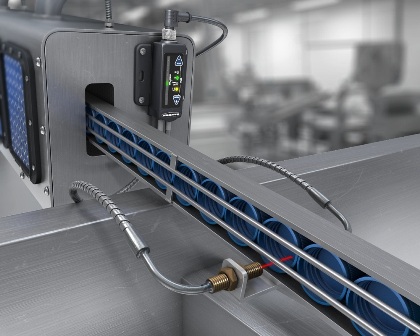
The beauty of fiber optic cables is that they transmit light instead of current.Configurations of different materials are possible, with different degrees of head sensitivity.
A diffuse fiber optic cable consists of a pair of facets, one of which goes to the amplifier and the other to the sensing head. At the same time, two cables are connected to the sensitive head — one for the light source, the other for the electronics.
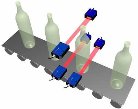
A single-beam fiber optic cable contains a pair of identical cables, each connected to an amplifier and having its own optical head. One cable is used to transmit light and the other to receive.
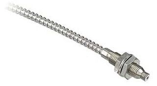
The fibers themselves are usually glass or plastic. Plastic — thinner, cheaper, more flexible. The glass is stronger and can work at higher temperatures. Plastic can be cut to length, but glass is only cut at the manufacturing stage. Fiber sheath — from extruded plastic to heavy-duty stainless steel braid.
The most important thing when choosing an optical sensor is to choose the right optical head. After all, it is precisely with the sensitivity of the head that the accuracy of detecting parts, whether small, stationary or moving, is related. At what angle will the receiver and emitter be located relative to the object, what is the permissible dispersion. Whether a round bundle of fibers is required to produce a round beam or an extended bundle to produce a horizontal projection.
As for the circular beams, in the diffuse head they can be uniformly branched with all the output fibers on one half and the receiving fibers on the other. This design is common, but can cause a delay when reading information from a part moving at right angles to the bifurcation line.
The uniform distribution of source and receiver fibers results in more uniform beams. Uniform beams allow you to equalize the effects of sending and receiving waves, and the detection will turn out regardless of the direction of movement of the object.
The type of optical head, cable length and amplifier have a significant effect on the optical viewing distance. It is difficult to give an exact estimate, but manufacturers indicate these data. A single beam sensor has a wider range than a diffuse sensor. Longer fibers, shorter range. Better amplifier — stronger signal, greater range.
Distributed I/O is increasingly used in industrial automation and it is possible to connect multiple cables from optical sensors to a single manifold.
Optical amplifiers are often stand-alone, single-channel DIN rail-mount devices, easily panel-mounted, and the only drawback is routing connections from individual amplifiers.
The collector can group multiple optical channels into one control center: the collectors are equipped with menu-driven displays and each channel is individually programmable. The configured channels can be used by the AND / OR logic, which greatly simplifies the control of the PLC.
The use of optical fibers performs well in systems operating under conditions of high electrical noise. Optical fibers do not pick up electrical noise and the electronic amplifier is protected by a cabinet. Small assembly lines with automated detection of parts on conveyors in the device assembly process is another very promising and already quite widespread application of optical sensors.
Heads with different orientation, different sizes, different dispersion to provide the desired degree of focusing accuracy, regardless of the size of the sensor — all this, together with the control logic, opens up a huge potential of possibilities. For example, one sensor detects the presence of a part where assembly begins, and the second confirms the end of assembly.
Also, regardless of the application, it is important to select the sensor and head with the parameters suitable for the user's required application: in terms of scattering, distance, sampling, option in terms of settings and programming.
The only downside is that you can't bend the fibers excessively. It is necessary to bend a little more and irreparable plastic deformation of the fibers will occur, the throughput will decrease or disappear completely. The allowable bend radius depends on the type of fiber and the size and dispersion of the fibers in the bundle. These characteristics should be considered when selecting a sensor for your application.