Unified analog signals in automation systems
When we create an automation system for a certain technological process, we somehow need to connect sensors and other signal devices — with actuators, with converters, with controllers, etc. The latter, as a rule, receive a signal from the sensor in the form of a voltage or current of a certain magnitude ( in the case of analog signals), or in the form of pulses with certain time parameters (in the case of digital signals).
The parameters of these electrical signals must in some very definite way correspond to the parameters of the physical quantity that the sensor fixes, so that the control of the end device is adequate to the task of automation.
Of course, it is most convenient to unify analog signals from different sensors, so that the controllers gain flexibility, so that the user does not have to choose his individual type of interface for each sensor and his own sensor for each interface.
Let the nature of the input-output signals become unified, the developers decided, since with this approach the development of automation systems and automation blocks for industry will be greatly simplified, and troubleshooting, maintenance and modernization of equipment will become much easier - flexible. Even if one sensor fails, you do not need to look for the exact same one at all, it will be enough to choose an analogue with the corresponding output signals.
Measurements of ambient temperature, engine speed, fluid pressure, sample mechanical stress, air humidity, etc. — are often performed by processing continuous analog signals received from the relevant sensors, while the continuous operation of the connected device is automatically corrected: heating element, frequency converter, pump, press, etc.
The most common analog signal is either a voltage signal ranging from 0 to 10 V or a current signal ranging from 4 to 20 mA.
Voltage control from 0 to 10 V
When a unified 0 to 10 V voltage signal is used, then this continuous sequence of 0 to 10 V voltages is associated with a series of measured physical quantities, such as pressure or temperature.
Assume that the temperature changes from -30 to +125°C while the voltage changes from 0 to 10V, with 0 volts corresponding to a temperature of -30°C and 10 volts to +125°C. This could be the temperature of the reactant or the workpiece, and the intermediate temperature values will have strictly defined voltage values of the specified range. Here the relationship is not necessarily linear.
In this way, it is possible to control various devices as well as obtain monitoring information. For example, a radiator with a thermal sensor has an analog output to display the current temperature: 0 V — the temperature of the surface of the radiator is + 25 ° C or lower, 10 V — the temperature has reached + 125 ° C — the maximum permissible.
Or by applying a voltage from 0 to 10 V from the controller to the analog input of the pump, we adjust the gas pressure in the container: 0 V — the pressure is equal to atmospheric, 5 V — the pressure is 2 atm, 10 V — 4 atm. similarly, you can control heating devices, metal cutting machines, valves and other fittings and actuators for various purposes.
Current control (4 to 20 mA current loop)
The second type of unified analog signal for automation control is a 4-20 mA current signal called a «current loop». This signal is also used to receive signals from various sensors in order to control the drives.
Unlike a voltage signal, the current nature of the signal allows it to be transmitted without distortion over much greater distances, as line voltage drops and resistances are automatically compensated. In addition, it is very easy to diagnose the integrity of transmission circuits — if there is current, then the line is intact, if there is no current, there is an open circuit. For this reason, the smallest value is 4 mA, not 0 mA.
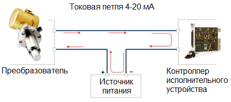
So here a current source is used as the power source for the control signal and not a voltage source. Accordingly, the drive controller must have a 4-20 mA current input, and the sensor transducer must have a current output.Suppose the frequency converter has a control current input of 4-20 mA, then when a signal of 4 mA or less is applied to the input, the controlled drive will stop, and when a current of 20 mA is applied, it will accelerate to full speed.
Meanwhile, current sensor outputs can be both active and passive. More often than not, the outputs are passive, which means that an additional power supply is required, which is connected in series with the sensor and the drive controller. A sensor or controller with an active output does not require a power supply as it is built-in.
The analog current loop is more commonly used in engineering today than voltage signals. It can be used at distances of up to several kilometers. To protect the equipment, galvanic isolation of optoelectronic devices such as optocouplers is used. Due to the imperfection of the current source, the maximum allowable line length (and the maximum line resistance) depends on the voltage from which the current source is supplied.
For example, with a typical supply voltage of 12 volts, the resistance should not exceed 600 ohms. The ranges of currents and voltages are described in GOST 26.011-80 «Measurements and automation. Input and output of continuous electric current and voltage».
Primary Signal Unification Tool - Normalization Converter
To unify the primary signal from the sensor — to convert it into a voltage from 0 to 10 V or into a current from 4 to 20 mA, the so-called normalizing converters… These standardizing converters are available for temperature, humidity, pressure, weight, etc.
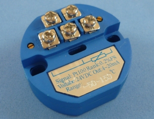
The principle of operation of the sensor can be different: capacitive, inductive, resistive, thermocouple, etc. However, for convenience in further processing of the signal, the output must meet the unification requirements. That is why sensors are often equipped with standard converters of the measured value into current or voltage.