Examples of LAD language programs for programmable logic controllers
One of the main and quite common programming languages industrial logic controllers (PLC) is a ladder logic language — Ladder Diagram (Eng. LD, Eng. LAD, Russian RKS).
This graphical programming language is based on the representation of switching diagrams and is convenient for the electrical engineer because the normally closed and normally open contact elements of the LAD language can be connected to normally closed and normally open switches in electrical circuits.
Since the mid XX Relay automation systems have been widely used in industry for centuries. In the early 70s. relay machines began to be gradually replaced by programmable controllers. For a while, both worked simultaneously and were staffed by the same people. Thus appeared the task of "transferring" the relay circuits to the PLC.
Various options for software implementation of relay circuits have been created by almost all leading PLC manufacturers.Due to its simplicity of presentation, LAD gained well-deserved popularity, which was the main reason for its inclusion in the IEC standard.
The syntax of LAD commands is very similar to the syntax of the Ladder description language. This representation allows you to trace the "energy flow" between the tires as it passes through the various contacts, components and output elements (coils).
Switching circuit elements, such as normally open contacts and normally closed contacts, are grouped into segments. One or more segments form a logical block code section.
The program interface, written in LAD language, is clear and simple, because the control LAD program is cyclic and consists of rows connected from the left by a vertical bus, and the flow or absence of current in the circuit corresponds to a result logical operation (true — current flows; false — no current).
Pictures 1 and 2 show segments of the program describing two actions for controlling the conveyor motor in the LAD language:
-
pressing any «Start» button starts the engine;
-
pressing any «Stop» button or activating the sensor will turn off the engine.

Rice. 1. Starting the engine after pressing any «Start» button
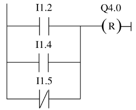
Rice. 2. Shutting down the engine after pressing any "Stop" button or triggering the sensor
The second task is to determine the direction of movement of the conveyor belt. Suppose two photoelectric sensors (REV 1 and REV 2) are installed on the belt to determine the direction of movement of the object. Both operate as normally open contacts.
In fig. 3 — 4 are presented segments of LAD language programs for three actions:
-
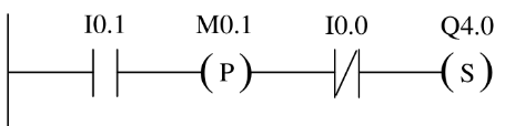
if at input 10.0 the signal changes from «0» to «1» (rising edge), and the state of the signal at input I0.1 is equal to «0», then the conveyor belt object moves to the left;
-
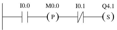
if at input 10.1 the signal changes from «0» to «1» (rising edge), and the state of the signal at input I0.0 is equal to «0», then the conveyor belt object moves to the right;
-
if both photosensors are covered, it means that the object is between the sensors.
Rice. 3. The movement of the object to the left if the input I0.0 changes the state from «0» to «1» and the input I0.1 is equal to «0»
Rice. 4. Move the object to the right if the input I0.1 changes from «0» to «1» and the input I0.0 is equal to «0»
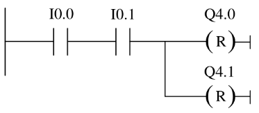
Rice. 5.Finding an object between the sensors
In fig. 3 — 4 notation adopted:
-
input 1.0 (REV 1) — photosensor # 1;
-
input 10.1 (REV 2) — photosensor # 2;
-
M0.0 (PMV 1) — time marker No. 1;
-
М0.1 (РМВ 2) — time marker No. 2;
-
output Q4.0 (LEFT) — left movement indicator;
-
output Q4.1 (RIGHT) — right movement indicator.
In fig. 6 — 9 present the simplest four-action timer programs:
-
if timer T1 atus is equal to «0», the time value of 250 ms in T1 starts and T1 starts as an extended pulse timer;
-
the timer state is temporarily stored in an auxiliary token;
-
if the state of the timer T1 is «1», go to label M001;
-
when timer T1 expires, tag word 100 is incremented by «1».
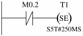
Rice. 6. Extended pulse start timer

Rice. 7… Temporarily storing the timer state in the auxiliary tag
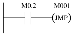
Rice. 8… Go to the label

Rice. 9… Increment the marker by «1» when timer T1 expires
Sample LAD language program for LOGO controller
The universal logic module LOGO! is a compact, functionally complete product designed to solve the simplest automation tasks with logical information processing.
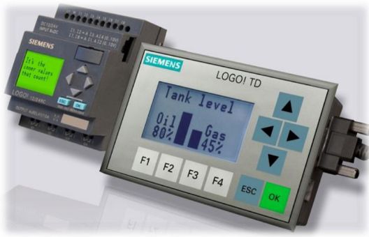
Rice. 10. LOGO module
Using the LOGO module! solved the problem managementI am a heating system in the shower cabins of the administrative and production building.
The composition of the heating system includes the following components:
-
three heating boilers used for space heating;
-
three pumps that circulate the coolant;
-
piping and heating registers.
The control system must control the temperature in the shower cabins, the pressure (the first level is low, at which further work is possible, provided that the filling system is turned on, and the second critical level, at which further work is prohibited) , as well as control of the temperature of the coolant in the heating system, lack of energy resources (electricity, gas).
In addition, additional sources of heating can be provided in the heating system, for example, electric heaters. Let the electric heaters come on three times a day: from 600 to 800; from 1500 to 1700; from 2300 to 0100… If for some reason the temperature is below normal at the time the workers visit the showers, then the electric heaters are turned on additionally.
The following are used as inputs and outputs:
-
AI1 — input signal from the pressure sensor for the critical pressure level of the coolant;
-
AI2 — input signal from the pressure sensor for a low level of coolant pressure, which allows further operation;
-
AI3 — input signal from the temperature sensor to increase the operating temperature of the coolant;
-
input 13 — input signal for lack of electricity;
-
input 14 — input signal for the lack of natural gas;
-
output Q1 — output signal that turns on the heating system (circulation pump #1);
-
output Q2 — output signal that turns on the filling system;
-
output Q3 is an output signal that turns off the boilers of the heating system (heating boiler No. 1);
-
output Q4 is an output signal that interrupts the gas supply to the boilers;
-
output Q5 — output signal that turns on the heating system (circulation pump #2);
-
output Q6 — output signal that turns on the heating system (circulation pump No. 3);
-
output Q7 is an output signal that turns off the boilers of the heating system (heating boiler No. 2);
-
output Q8 is an output signal that turns off the boilers of the heating system (heating boiler No. 3);
-
C2 — start button.
-
The B001 is a seven-day timer with three modes.
For electric heaters:
-
AI1 — input signal from the temperature sensor for the temperature in the shower rooms;
-
output Q1 — output signal that turns on the electric heaters (electric heater No. 1);
-
output Q2 — output signal that turns on the electric heaters (electric heater No. 3);
-
output Q3 is an output signal that turns on the electric heaters (electric heater #3).
A program for an automated heating control system written in a programming language in the form of relay contact symbols (LAD) in the software package «LOGO! Soft comfort» shown in fig. 11 and 12.
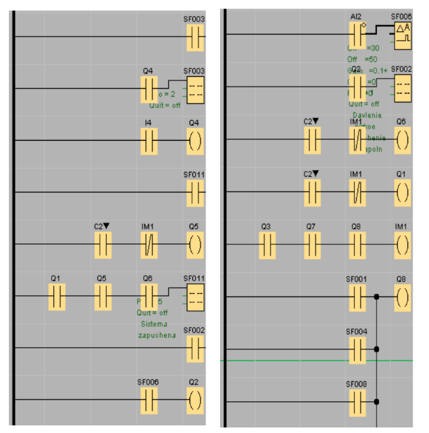
Rice. eleven. First FraG the LAD language program
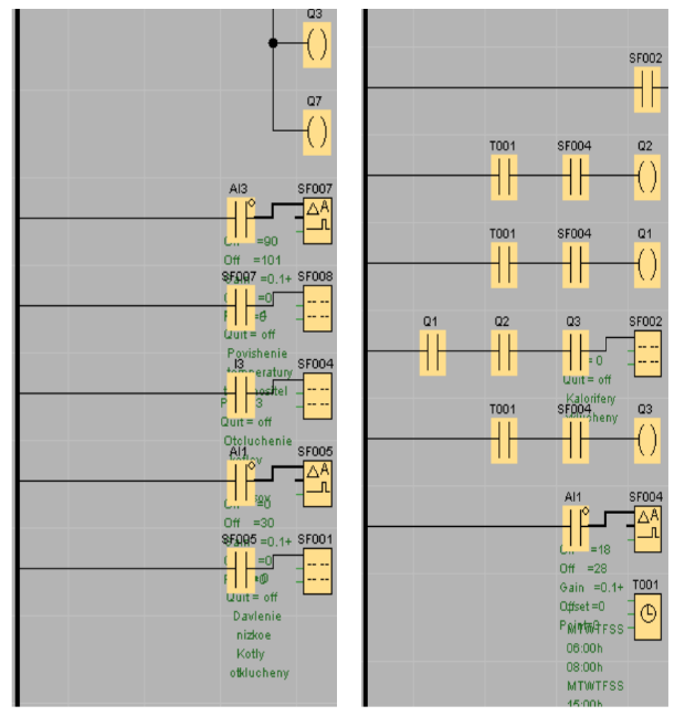
Rice.12… The second fragment of the LAD language program