Tank water level control using OWEN PR110 programmable relay
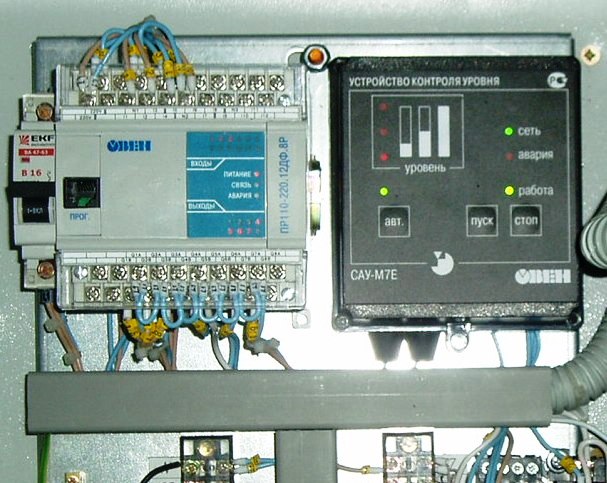
The PR110 controller is manufactured by the Russian company «OWEN». The controller performs operations on discrete signals only — its main purpose is to replace simple control systems based on relay logic. This determines the fact that it (as well as other controllers with similar functions) is assigned the name «programmable relay».

ARIES PR110 Programmable Relay Functional Diagram:
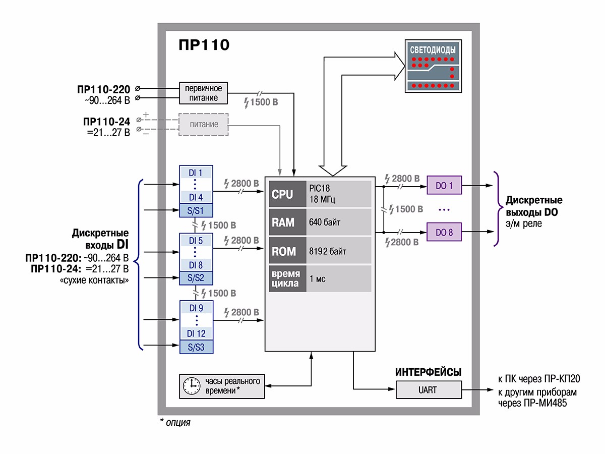
The primary and only tool for programming and debugging controller software is a personal computer. With its help, you can not only create the software of the corresponding controller, but, as a rule, also observe how it works using computer simulation.
We will look at the process of creating a switching control program for PR110 programmable relays using the example of a water level control system in a tank.
Technical conditions
It is necessary to implement a control system for filling the tank with water. The performance of certain functions is determined by the state of the level sensors, some functions by the operator. There should be a light indication of the current system status.
The control algorithm is as follows. There are three sensors that determine the current water level in the tank: upper, middle and lower. Each sensor is triggered (outputs a logic unit level at the output) when the water exceeds the corresponding level.
Manual control is carried out using two buttons: «Start» and «Stop». When the tank is empty (the water level is below the lower level sensors), the red indicator light should be steady, when it is full (above the upper), it should be steady green. Two pumps are controlled.
The pumps can be started if the tank is not full (the water level is below the top). If by pressing the «Start» button the water level is below the average - both pumps are started, if by pressing the «Start» button the water level is above the average - one pump is started.
Turning on the pumps is accompanied by a flashing green indicator. When the tank is full (the water level reaches the upper level), the pumps turn off automatically. If the tank is empty (the water level is below the lower level), it is not possible to turn off the pumps by pressing the «Stop» button.
An example of creating a program in OWEN Logic
To accomplish this task, the control machine must have five discrete inputs and four relay outputs. To solve this problem, we will make the following decisions.
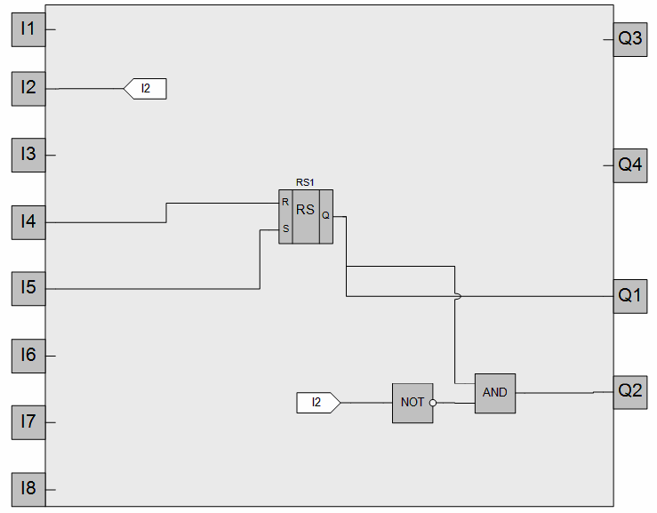
Connect the lower tank water level sensor to input I1, the middle level sensor to input I2 and the upper level sensor to input I3.Connect the Stop button to input I4 and the Start button to input I5. We will control the inclusion of pump No. 1 with the help of the output Q1, the inclusion of the pump No. 2 — with the help of the output Q2. Connect the red indicator to output Q3, the green indicator to output Q4.
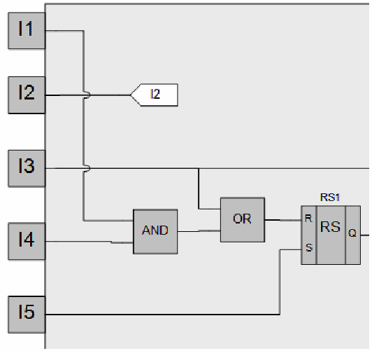
Manual control is carried out by means of buttons that generate short-term control signals. In order for the control system to remain in a state in which we will transfer it with a short-term signal from one or another button, a trigger is needed in the program.
Let's introduce flip-flop RS1 into the program. The output of this flip-flop is set to one when a positive edge arrives at input S and resets to zero when a positive edge arrives at input R. It should be noted that when the one signals arrive at the inputs, R input signal is priority.
If the water level in the tank is higher than the above or we have pressed and held the "Stop" button in this state, then pressing the "Start" button at that time should not turn on the pumps. Therefore, the «Start» button is connected to the input S with a lower priority of the flip-flop RS1. Then, if no conditions prevent the pump from turning on (ie there will be a logic zero at the R input of trigger RS1), when the «Start» button is pressed, the output of trigger RS1 will be set to one. This signal will be used to activate the motors.
Of the two pumps, pump #1 must be turned on in any case, so the signal from the RS1 trigger output is connected to the Q1 output. Pump #2 should only turn on if the mid level sensor is not triggered. To fulfill this condition, we introduce the inverter and logic element AND into the program.The input of the inverter is connected to the input I2, the inputs of the logic element AND to the output of the inverter and to the output of the trigger RS1, respectively.
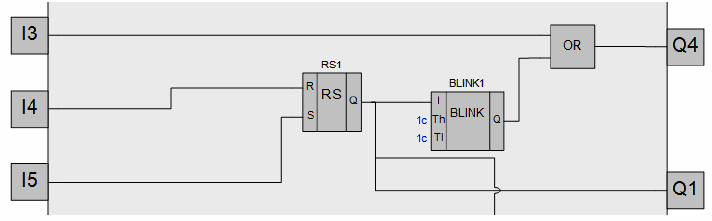
Turning on the pumps should be accompanied by a flashing green indicator. To generate a periodic signal to turn on / off the green indicator, we introduce the BLINK1 square wave generator into the program. In the properties tab of this block, set the duration of one and zero signals at its output to be equal and equal to 1s. Connect the output of the trigger RS1 to the input of the activation of the operation of the generator BLINK1.
Now the BLINK1 generator will only work when the trigger output RS1 is set to one ie. when the pumps are activated. 26 Let's introduce the OR gate into the program. We connect its output to the output of Q4. We connect one input of the OR gate to the output of the generator BLINK1, the other to the input I3. Now, when the pumps are on, the green indicator will flash, but if the top level sensor is triggered, this indicator will be on continuously.
The pumps should be turned off if we press the "Stop" button and at the same time the lower level sensor will be in a logic unit state (presence with at least minimal water in the tank) or if the upper level sensor is triggered (the tank is full).
To fulfill these conditions, we introduce the logic element OR and the logic element I into the program. We connect one input of the logic element AND to the "Stop" button, the other to the input I1 (with the output of the lower level sensor). We connect one input of the OR element to the output of the AND element, the other to input I3 (with the output of the upper level sensor). The output of the OR element is connected to the R input of the flip-flop RS1.
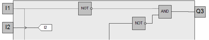
The red indicator should light up if two conditions are met at the same time: the pumps are not working (zero is present at the output of the trigger RS1) and the water level is below the lower level (there is zero at the output of the lower level sensor).
To "check" these conditions and control the red indicator in the program, we introduce two inverters and a logic element I. The input of one inverter is connected to the input I1 (with the output of the lower level sensor), the input of the other inverter - with the trigger output RS1). We connect the outputs of the inverters to the inputs of the AND gate. The output of the AND gate is connected to the output of Q3.
In the end, in general, you should have the program presented below. The figure tentatively shows external circuits connected to a programmable relay.
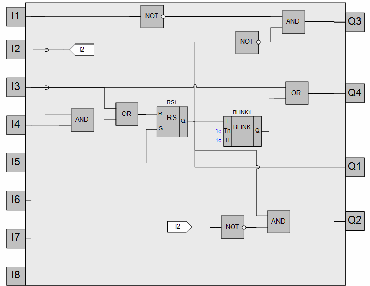
Using the emulation mode of the OWEN Logic programming environment, ensure that the program works according to the original task. After loading the program into the relay, ensure the same.