How the 4-20 mA circuit works
The "current loop" was used as a data transmission interface in the 1950s. At first, the operating current of the interface was 60 mA, and later, starting in 1962, the 20 mA current loop interface became widespread in the teletype.
In the 1980s, when various sensors, automation equipment and actuators began to be widely introduced in technological equipment, the “current circuit” interface narrowed the range of its operating currents — it began to vary from 4 to 20 mA.
The further spread of «current loop» began to slow down from 1983, with the advent of the RS-485 interface standard, and today «current loop» is almost never used in new equipment as such.
A current loop transmitter differs from an RS-485 transmitter in that it uses a current source rather than a voltage source.
The current, unlike the voltage, moving from the source along the circuit, does not change its current value depending on the load parameters. Therefore, the «current loop» is not sensitive to either cable resistance, load resistance, or even inductive noise EMF.
In addition, the loop current does not depend on the supply voltage of the current source itself, but can only change due to leakages through the cable, which are usually insignificant. This characteristic of the current cycle completely determines the ways of its implementation.
It should be noted that the EMF of the capacitive pickup is applied here in parallel with the current source, and the shielding is used to weaken its parasitic effect.
For this reason, the signal transmission line is usually a shielded twisted pair, which, working together with a differential receiver, alone attenuates common mode and inductive noise.
On the receiving side of the signal, the loop current is converted to voltage using a calibrated resistor. And at a current of 20 mA, a voltage of the standard series 2.5 V is obtained; 5V; 10V; — it is enough only to use a resistor with a resistance of 125, 250 or 500 Ohm respectively.
The first and main disadvantage of the «current loop» interface is its low speed, limited by the speed of charging the capacity of the transmission cable from the above-mentioned current source located on the transmitting side.
So, when using a cable 2 km long, with a linear capacitance of 75 pF / m, its capacitance will be 150 nF, which means that it takes 38 μs to charge this capacitance to 5 volts at a current of 20 mA, which corresponds to a data transfer rate of 4.5 kbps.
Below is a graphical dependence of the maximum available data transmission rate through the «current loop» on the length of the cable used at different levels of distortion (jitter) and at different voltages, the evaluation was carried out in the same way as for the RS Interface -485.
Another disadvantage of the «current loop» is the lack of a specific standard for the design of connectors and for the electrical parameters of the cables, which also limits the practical application of this interface. In fairness, it can be noted that in fact, the generally accepted ones range from 0 to 20 mA and from 4 to 20 mA. The range 0 — 60 mA is used much less often.
The most promising developments that require the use of the "current loop" interface, for the most part today use only the 4 ... 20 mA interface, which makes it possible to easily diagnose a line break. In addition, the "current loop" can be digital or analog, depending on the developer's requirements (more on that later).
The practically low data rate of any type of «current loop» (analog or digital) allows it to be used simultaneously with several receivers connected in series, and no matching of long lines is required.
Analogue version of «current loop»
The analog "current loop" has found application in technology where it is necessary, for example, to transmit signals from sensors to controllers or between controllers and actuators. Here, the current cycle provides several advantages.
First of all, the range of variation of the measured value, when it is reduced to the standard range, allows you to change the components of the system. The ability to transmit a signal with high accuracy (no more than + -0.05% error) over a considerable distance is also remarkable. Finally, the current cycle standard is supported by most industrial automation vendors.
The 4 … 20 mA current loop has a minimum current of 4 mA as the signal reference point.Thus, if the cable is broken, the current will be zero. While using a 0 … 20 mA current loop, it will be more difficult to diagnose a cable break, as 0 mA may simply indicate the minimum value of the transmitted signal. Another advantage of the 4 … 20 mA range is that even at a level of 4 mA it is possible to power the sensor without any problems.
Below are two analog current diagrams. In the first version, the power supply is built into the transmitter, while in the second version, the power supply is external.
The built-in power supply is convenient in terms of installation, and the external one allows you to change its parameters depending on the purpose and operating conditions of the device with which the current loop is used.
The principle of operation of the current loop is the same for both circuits. Ideally, an op-amp has an infinitely large internal resistance and zero current at its inputs, which means that the voltage across its inputs is also initially zero.
Thus, the current through the resistor in the transmitter will depend only on the value of the input voltage and will be equal to the current in the entire loop, while it will not depend on the load resistance. Therefore, the receiver input voltage can be easily determined.
The op-amp circuit has the advantage of allowing you to calibrate the transmitter without having to connect a receiver cable to it, since the error introduced by the receiver and cable is very small.
The output voltage is selected based on the needs of the transmission transistor for its normal operation in active mode, as well as with the condition for compensating the voltage drop on the wires, the transistor itself and the resistors.
Say the resistors are 500 ohms and the cable is 100 ohms. Then, to obtain a current of 20 mA, a voltage source of 22 V is required. The nearest standard voltage is chosen — 24 V. The excess power from the voltage limit will simply be dissipated on the transistor.
Note that both charts show galvanic isolation between the transmitter stage and the input of the transmitter. This is done to avoid any false connection between the transmitter and the receiver.
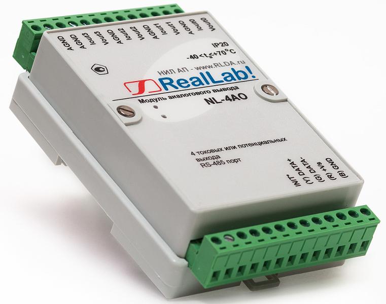
As an example of a transmitter for building an analog current loop, we can cite a finished product NL-4AO with four analog output channels for connecting a computer with an actuator using the 4 ... 20 mA or 0 ... 20 mA » current cycle « protocol.
The module communicates with the computer via RS-485 protocol. The device is current calibrated to compensate for conversion errors and executes commands supplied by the computer. The calibration coefficients are stored in the device memory. Digital data is converted to analog using a DAC.
Digital version of «current cycle»
The digital current loop works, as a rule, in the 0 ... 20 mA mode, since it is easier to reproduce the digital signal in this form. The accuracy of the logic levels is not so important here, so the loop current source can have a not very high internal resistance and relatively low accuracy.
In the diagram above, with a supply voltage of 24 V, 0.8 V is dropped at the input of the receiver, which means that with a resistor of 1.2 kΩ, the current will be 20 mA. The voltage drop in the cable, even if its resistance is 10% of the total loop resistance, can be neglected, as can the voltage drop across the optocoupler.In practice, under these conditions, the transmitter can be considered a current source.