Packet switches and switches
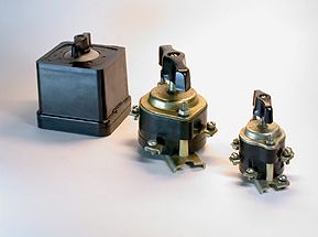
Package switches are used to turn on and off electric circuits with direct and alternating current up to 100 A at a voltage of 220 V and up to 60 A at a voltage of 380 V. Package switches and switches are much more compact than knife switches. Batch switches are mounted with only the handle on the panel, which ensures the safety of the operating personnel.
The device of packet switches
A packet switch consists of a switching mechanism and a contact group. The fixed contact terminals protrude from the housing. The movable contacts are located inside the housing on a square sleeve made of insulating material. The body is assembled from insulating washers connected to each other by tightening pins. Movable contacts are cranked by a spring-loaded quick-change mechanism.
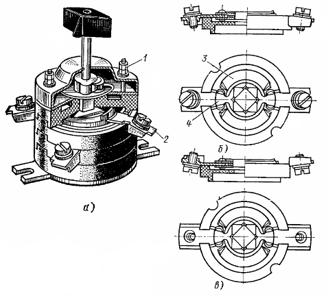 Package lock PV type: a — general view, b — front link package, c — back link package
When the handle is turned, the spring of the quick-change mechanism is wound first.When the force acting from the handle on the shaped washer increases to a certain value, the washer very quickly rotates a quarter turn to the next stop in the top cover.
The lid stops are located at an angle of 90 °. A square sleeve, on which the movable contacts are fixed, is connected with a shaped washer. Simultaneously with the rapid rotation of the figure washer, the moving contacts rotate. The latter are reinforced in fiber plates, which act as guides and ensure rapid extinguishing of the emerging arc.
Fibers give off a lot of gas when exposed to high temperatures. Their pressure increases, as a result of which gases move through the gaps of the package. Fresh, non-ionized air entering the interior of the breaker facilitates rapid arc extinguishment.
Batch switches are produced for currents of 10 and 25 A at a voltage of 220 V in one-, two- and three-pole versions. The latter are used to turn on three-phase asynchronous motors (for example, in universal drives). V three-pole bursting switch three movable contacts are located between four insulating washers. The same package switches can be used at a voltage of 380 V, but the permissible current value for them is reduced to 6 and 15 A, respectively.
At rated currents and voltages and a power factor of 8.0, the circuit breakers can withstand 20,000 operations. The switching frequency should not exceed 300 per hour.
For convenience when connecting the wires, the fixed contacts are not located along the former, but are offset relative to each other. The terminals of one contact are located diametrically oppositely between the same washers.It is customary to connect the wires from the receiver to the terminals located on one side of the pins and the mains wires to the other.
By turning the handle of the batch switch 90 °, you can turn the receiver on and off. Of the four positions on the packet switch handle, two correspond to the on and off states of the receiver.

Batch switches
In addition to quick switches, widespread ones are also widely used. In the burst switch, only one position corresponds to the off state of the receiver, and the other three correspond to the on state in various ways.
The figure shows a circuit diagram of a three-speed motor M with a batch switch Q. A four-position batch switch has six movable contacts. One position (0) corresponds to the disabled state of the motor. The motor stator contains two windings, one of which is star connected and the other can be switched from delta to double star.
Scheme of inclusion by batch switching of the three-stage electric motor
According to the diagram, in position 1 of the handle, the motor is connected to the network through terminals ЗС1, ЗС2, ЗСЗ3. In the stator of the motor it rotates magnetic field with three pairs of poles. The motor synchronous speed (magnetic field speed) is 1000 rpm.
The connection between the left and right terminals of the switch is indicated by dots with lines shown vertically below the numbers corresponding to the positions of the switch handle.position 1 of the switch handle, the upper left terminal is connected to motor terminal 3C1, the middle left terminal is connected to terminal 3C2, and the lower left terminal is connected to terminal 3C3.
In position 3 of the handle, along with the connection of the left terminals of the switch to the terminals 1C1, 1C2, 1C3 of the motor, the terminals 2C1, 2C2 and 2C3 are connected together. This ensures the connection of the winding in a double star with the formation of one pair of poles and obtaining a synchronous speed of 3000 rpm.
In position 2 of the switch handle, the upper left terminal is connected to motor terminal 2C1, the middle left terminal is connected to terminal 2C2, and the lower left terminal is connected to terminal 2C3. In this case, the motor is connected in a triangle with the formation of two pairs of poles and obtaining a synchronous speed of 1500 rpm.
3-pole switch
It differs from a three-pole switch in that the movable contacts (knives) have not one, but two closed positions. The knives can be closed with three left and three right fixed contacts. Such switches are used to turn on three-phase motors and change the direction of their rotation (reversal) of a three-phase motor by switching two current supply wires.
Package switches and IP56 protection switches are manufactured in a non-flammable, impact-resistant plastic housing.