Control of the operating modes of the electrical equipment of transformer substations
 To ensure trouble-free operation transformer substations it is necessary to control the operating modes of the electrical equipment: the load on the individual connections, the voltage and frequency at the control points of the power transmission networks, the value and direction of the flows of active and reactive power, the amount of supplied energy.
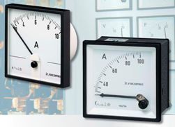
Control of compliance with factory parameters and other technical indicators of the operation of electrical equipment is carried out mainly with the help of panel equipment, and in some cases, if necessary, portable measuring devices are used.
Electrical switchboards used in substations have an accuracy class of 2.5-4.0. Panel voltmeters with an accuracy class of 1.0 are used in the control points of the power system. Accuracy class means the largest reduced error β of the instrument as a percentage of the maximum tax reading allowed by the scale of the instrument, i.e.
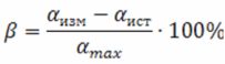
where stork is the measured value of stork is the true value determined by the sample device; atax — maximum instrument scale readings.
Various types of electrical measuring devices are used to control the operating modes of electrical equipment at substations: magneto-electric, electromagnetic, electrodynamic, induction, digital and self-recording, as well as automatic oscilloscopes. In order to control the nominal value of the measured value, a red line is drawn on the scale of the device, which makes it easier for the duty personnel to monitor the operation mode of the electrical equipment and helps to prevent unauthorized overloads.
Magnetoelectric devices are used for measurements in DC circuits. They have the same scale, allow you to make measurements with great accuracy, are not affected by magnetic fields and fluctuations in the temperature of the surrounding air. For measurement in AC circuits, these devices are used together with rectifiers.
Electromagnetic devices are mainly used for measurement in AC circuits and are widely used as switchboards. Their accuracy is lower than that of magnetoelectric devices.
Electrodynamic devices have two coils located inside each other, the opposite moment is created by a spring. These devices are convenient for measuring electrical parameters that are the product of two quantities (for example, power). Electrodynamic wattmeters measure power in AC and DC circuits. Devices of this system have a weak internal magnetic field, during operation they are subject to the influence of external magnetic fields and consume significant power.
Induction devices operate on the principle of a rotating magnetic field and can only work in alternating current circuits. They are used as wattmeters and electricity meters.
Electronic digital devices have, as a rule, a high accuracy class (0.1 — 1.0), high speed, which allows you to observe rapid changes in the measured value, the ability to read the readings directly in numbers. Such devices are used as frequency meters (F-205), as well as DC and AC voltmeters (F-200, F-220, etc.).
Recorders are used for continuous recording of current, voltage, frequency, power and allow documentary recording of the most important performance indicators of electrical equipment, which facilitates the analysis of normal modes and emergency situations in the power system.
Automatic light beam oscilloscopes refer to devices designed specifically for recording and analyzing emergency processes in power systems.
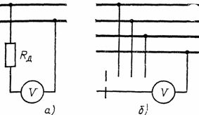
The load is monitored using ammeters connected in series to the measuring circuit. Devices for high currents are difficult to implement, therefore, when measuring direct current, ammeters are connected through shunts (Fig. 1, a), and for alternating current - through current transformers (Fig. 1, b, c).
The connection and disconnection of devices to shunts and secondary windings of current transformers can be carried out under voltage and without disconnection of the load in the primary circuit, in accordance with the relevant safety rules.
AC ammeters are installed where systematic process control is required; in all circuits above 1 kV, if there are current transformers used for other purposes, and in circuits with a voltage of up to 1 kV, measurement of the total current of all connected electrical consumers (and sometimes for individual electrical consumers).
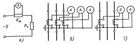
Rice. 1. Connection diagrams of ammeters for measuring alternating and direct current
Direct current ammeters are installed in rectifier circuits, in excitation circuits of synchronous compensators, in battery circuits.
To control the load in alternating current circuits with a voltage of 0.4-0.6-10 kV, portable devices are used - electric clamp (types Ts90 for 15-600 A, 10 kV, Ts91 for 10-500 A, 600 V). In fig. 2 shows a general view and diagram of the Ts90 electrical clamp.
The clamp meter consists of a current transformer with a split magnetic circuit 1, equipped with handles 4 and an ammeter 3. When measuring, the magnetic circuit of the clamp must cover the current-carrying wire 2 so that it does not touch it or neighboring phases. The jaws of the detachable magnetic chain must be firmly pressed.
When measuring with an electric clamp, all the requirements of the safety rules must be observed (the use of dielectric gloves, the location of the measuring device in relation to live parts of the electrical installation, etc.). In the clamp meter circuit (Fig. 2, b), the measuring device (ammeter) is connected to the secondary winding of the clamp current transformer using a bridge over resistors and diodes. Additional resistors R1 — R10 allow five measurement ranges (15, 30, 75, 300, 600 A).
The voltage level is monitored using voltmeters in all bus sections with all voltages, both direct and alternating current, which can work separately (it is allowed to install one voltmeter with a switch for several measurement points). To measure voltage, voltmeters are connected in parallel in the measuring circuit. If it is necessary to extend the measurement limits, additional resistors are connected in series with the instruments.
Schemes for turning on voltmeters with additional resistors and using switches are shown in fig. 3. Additional resistors are used for measurements in DC and AC circuits up to 1 kV.
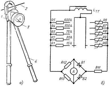
Rice. 2. Electric measuring clamps: a — general view; b — scheme
When measuring voltage in alternating current networks above 1 kV, voltage transformers are used. Schemes for connecting voltmeters through voltage transformers are shown in fig. 5. The nominal voltage of the secondary winding of the voltage transformer in all cases is equal to 100 V regardless of the nominal voltage of the primary winding, and panel voltmeters are calibrated taking into account the transformation ratio of the voltage transformer in units of primary voltage.
Measurement of AC and DC power produced using wattmeters. In substations, AC power (active and reactive) is mainly measured: on transformers, 110-1150 kV power lines and synchronous compensators. In addition, devices for measuring reactive power — varmeters do not differ in structure from wattmeters that measure active power. Only the connection schemes are different.The scheme of a wattmeter (varmeter) through current and voltage transformers (in electrical installations above 1 kV) is shown in fig. 5.
Rice. 3. Schemes for switching a voltmeter: a — with an additional resistor; b — using the switch
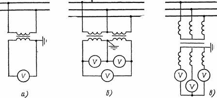
Rice. 4. Schemes for including voltmeters with voltage transformers: a — in single-phase networks; b — open triangle diagram; in-through three-phase two-winding transformer
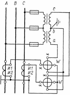
Rice. 5. Wiring diagram of a two-element wattmeter (two single-phase wattmeters)
When the wattmeter is switched on, the start of the voltage winding (marked *) must be connected to the terminal of the secondary winding of the voltage transformer of the phase in which the current transformer is connected. And when the varmeter is turned on, the voltage winding of the device is connected to the windings of the voltage transformer of other phases (in Fig. 5 it is necessary to change the terminals a and from the secondary winding of VT).
If the direction of the measured power of the connections (transformer, line) can change its direction depending on the mode, then in this case the wattmeters or varmeters must have a two-sided scale with a zero division in the middle of the scale.
To measure energy, active and reactive energy meters are used in alternating current circuits. There is calculated and technical measurement of electricity.Accounting accounting (meters) is used for monetary settlements with consumers for the supplied electricity, and technical accounting (control meters) is used to control the consumption of electricity in enterprises, power plants, substations (for example, for own needs: cooling transformers, heating of keys and their drives, etc., etc.).
For the electricity recorded by the control meters, no monetary settlements are made with the electricity supply organization. In substations, meters for active and reactive energy are installed on the high and medium voltage side, and in the absence of current transformers on the high voltage side, meters can be installed on the low voltage side.
Calculated meters for active energy are installed on the intersystem lines for each line leaving the substation (except for lines belonging to consumers and having meters at the receiving end). Reactive energy meters on cable and overhead lines up to 10 kV, departing from power system substations, are installed in cases where the calculation with industrial users is carried out using active energy meters on these lines.
In principle, meter switching circuits are no different from wattmeter switching circuits. Universal meters are connected through current and voltage transformers with secondary values of 5 A and 100 V respectively.
On these lines and transformers, where the energy flow can change in direction, plug meters are installed that measure electricity in one direction only.
Frequency control in buses of electrical substations outsourced by frequency counters... Currently electronic counters are used. Devices of this type have a complex circuit assembled on integrated elements (microcircuits) and are devices with increased accuracy (they measure the frequency with an accuracy of hundredths of a hertz). Frequency meters are included in the secondary circuits of voltage transformers in the same way as voltmeters.