Ringing cables
 For the correct connection of cables to the contacts of electrical machines, devices and devices, they are rings.
The simplest continuity of cables is carried out using a lamp and a battery, that is, the wires at one end of the cable (on the left of the figure) are arbitrarily marked and a battery wire is connected to the first of them. A wire is then connected to the lamp and the wires at the other end of the wire are touched in series with it. If the lamp lights up when touched, this is the core to which the battery wire is connected.
Continuity can also be done without a wire connecting the two ends of the cable. The same is the principle of continuity with the use of a megohmmeter, if it turns out that it is connected to the ends belonging to the same core, its arrow shows zero.
The considered dialing methods are convenient if the two ends of the cable are located close to each other and one person can perform it. If the ends of a long cable are located in different rooms of a building or in different buildings, the most universal method of dialing is the use of two handsets.
For this purpose, the telephone and microphone capsules in the pipes are connected in series, and a dry cell or battery with a voltage of 1-2 V is included in this scheme. This method is also convenient because the installers can coordinate their actions by talking on the phone.
At one end of the cable, the installer connects one wire of the pipe to the cable sheath and the other to one of its conductors. At the other end of the cable, a second worker connects one wire of the pipe to the sheath of the cable and the other in series to its cores. If a click is heard in the pipe and the fitters are heard, then the conductors of the pipe are attached to the same core of the cable.
In some cases, continuity is achieved using a special transformer with several taps from the secondary winding (Figure 10.18, d). In this case, the beginning of the winding is connected to the grounded cable sheaths, and the taps are connected to its cores. Each of the cores is then supplied. By measuring the voltage between the wires and the sheath at the opposite end of the cable and using the recorded voltage values, it is easy to determine whether the ends belong to one wire or the other and mark it.
To mark the conductors of power cables, use pieces of vinyl pipe or special end fittings marked with indelible ink.
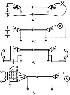
Rice. 1. Wiring continuity schemes: a, b — using a lamp, c — using a telephone headset, d — using a special transformer
Phase cables
To increase the reliability of the power supply to users, as well as in the event that the power of one power cable is not sufficient for the normal operation of the electrical installation, several parallel cables are used. In this case, they must be connected to electrical equipment in accordance with the phase sequence. If this condition is not met, turning on the power will cause a short circuit.
Determining the order of phase rotation when connecting cables in parallel is called cable phasing.
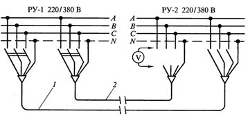
Let it be busbars from two switchgears (Fig. 2) connected to cable 1, through which electricity is transmitted from RU-1 to RU-2. For greater power supply reliability, cable 2 is laid parallel to the working cable, and its cores must also be connected to the busbars so that bus A in RU-1 is connected to bus A in RU-2. This requirement also applies to B and B buses.
Rice. 2. Cable phasing
In installations with a voltage of 380/220 V, the cable is phased using a voltmeter designed for the mains voltage of the network, i.e. the bus to which it is expected to be connected.
If the voltmeter shows mains voltage, it means that the cable core and the switchgear busbar are on different phases and cannot be connected. The zero reading of the voltmeter indicates that the cable core and the bus have the same potential and therefore belong to the same phase and therefore their connection is possible. The other two wires of the cable are phased in the same way.
In the absence of a voltmeter, you can use two series-connected incandescent lamps with a nominal voltage of 220 V (the core and the bus, when turned on, between which the lamps do not burn, belong to the same phase).
It must be remembered that since the cables are of considerable capacitance, after phasing, continuity and testing, a considerable voltage remains on their cores caused by the residual capacitive charge. Therefore, after each supply of voltage to the cable, it must be discharged by connecting each core to the grounding system.