Portable grounding
Purpose of portable grounding
Portable earthing is designed to protect people working on disconnected parts of live equipment or electrical installations from electric shock in the event of a wrong supply of voltage to the disconnected section or when an induced voltage appears on it.
Portable grounding is used in those parts of the electrical installation that do not have fixed grounding blades.
The protective effect of portable grounding or stationary grounding knives is that they do not allow voltage dangerous to personnel to appear outside the place of their installation.
When voltage is applied to a ground and a short circuit, a short circuit occurs. Therefore, the voltage at the short circuit point is reduced to almost zero and the voltage will not enter the live parts behind the ground. In addition, the protection will work and turn off the voltage source.
Portable grounding device
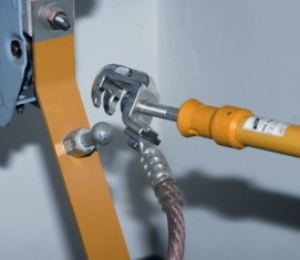
Portable grounding consists of: wires for grounding and short-circuiting between the current-carrying parts of different phases of the electrical installation and clamps for connecting the wires to the grounding wires and to the current-carrying parts.
The grounding and short wires are made of soft tough flexible bare wire.
Portable grounding devices are made as three-phase (for short-circuiting the three phases and grounding with a common grounding wire) and single-phase (for grounding live parts of each phase separately). Single-phase portable earthings are used in electrical installations with a voltage above 110 kV, because there the distances between the phases are large and the short wires are too long and heavy.
Requirements for portable grounding
The main requirement for portable grounding is their thermal and dynamic resistance to short-circuit current.
Clamps with which conductors are fixed to live parts must be such that they cannot be torn off by dynamic forces.
In addition, the clamps must provide a very reliable contact. Otherwise, they will overheat and burn during a short circuit.
When a short circuit current flows, the short circuit wires become very hot. Therefore, they must be thermally stable enough to remain intact during tripping by the short-circuit protection relay. It should be borne in mind that copper melts at a temperature of 1083 ° C.
The thermal stability of the wires is important, because when the wires are heated and broken, the working voltage of the electrical installation may appear at their ends.
The minimum cross-section is accepted for reasons of mechanical strength: for electrical installations with a voltage above 1000 V — 25 mm2 and for electrical installations with a voltage below 1000 V — 16 mm2. Conductors may not be used smaller than these cross-sections.
For electrical installations with a voltage of 6 — 10 kV with significant short-circuit currents, portable grounding wires with a very large cross-section (120 — 185 mm2), heavy and difficult to use, are obtained. In such cases, it is allowed to use two or more portable earths, installing them in parallel, side by side.
Calculation of the cross-section of portable grounding wires is done according to a simplified formula:
S = ( Azusta √Te ) / 272,
where Azusta-stationary short-circuit current, A, Te — fictitious time, sec.
For practical purposes, the value Te can be taken as equal to the time delay of the main relay protection of the connection of the electrical installation, the switch of which must break the short circuit at the point of the portable earth.
In order not to produce portable earths with different cross-sections for switchgear of the same voltage, the maximum time is usually taken as the design delay.
In networks with a grounded neutral, the cross-section of the wires is calculated from the single-phase short-circuit current, while in a system with an isolated neutral, it is sufficient to ensure thermal stability in the event of a two-phase short-circuit.
It is not allowed to use an insulated wire for grounding wires, since the insulation does not allow timely detection of damage to the conductors of the wires, which reduces its structural cross-section and can lead to burns from short-circuit current.
The construction of the clamps for connecting the wires must ensure the possibility of their reliable and permanent attachment to live parts with the help of a special rod for installing grounding. Short wires are connected directly to the terminals without adapters. This requirement is explained by the fact that terminals can have unsatisfactory contacts that are difficult to detect, but which can burn out when a short circuit current flows.
The connection of the short conductors of three-phase grounding to each other and to the grounding conductor is made firmly and reliably by welding or welding. A bolted connection can also be made, but in addition to the bolts, the connection must be soldered. Solder-only connection is not allowed, as the heating of the ground during flux can reach hundreds of degrees, at which point the solder will melt and the connection will break.
Rules for installing portable grounding
 Portable earths are installed on live parts on all sides, from where voltage can be supplied to the area disconnected from operation.
If the section on which the work is carried out is divided by a switching device (switch, disconnector) into parts or in the process of work it violates the integrity of the current-carrying parts of the section (part of the wires are removed, etc..), then if there is a danger of induced voltage from adjacent lines on any individual section, the location must be earthed.
The earthing installation is done with an insulating rod that is integral with the earthing or used for alternating operation with the terminals of all phases.
First, the grounding wire is connected to the grounding wiring or to a grounded structure, then after checking the absence of voltage on live parts with a voltage indicator using a stick, the grounding clamps are sequentially applied to live parts of all phases and fixed there also with a rod. If the rod is not suitable for fastening the clamps, the fastening can be done manually with dielectric gloves.
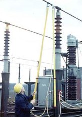
When installing grounding in switchgear, operations should be performed from the floor or ground, or from a ladder, without climbing over equipment that is not already grounded. If it is impossible to install and fix the grounding of the buses from the ground or stairs in an open switchgear, then it is possible to climb the equipment (transformer, circuit breaker) for this purpose only after a complete check of the absence of voltage at all inputs.
Climbing the structure of a disconnector with a voltage of 35 kV and above, which is live on one side, is unacceptable under any circumstances, since the person installing the earthing can be in dangerous proximity to live parts that remain live. An electric shock has occurred during such operations.
It should be noted that there is no induced voltage on the live part only when the ground is connected to it. Therefore, even after removing the charge from the live part or after removing the ground, it is unacceptable to touch ungrounded live parts without protective equipment.
All operations for installation and removal of portable grounding are carried out with the help of dielectric gloves.
Removal of portable grounding
When removing the ground, the clamps are first removed from the live parts, then the ground wire is disconnected.
In electrical installations with a voltage of more than 110 kV, the earthing must be removed using rods, even if at the place of installation it is possible to carry out an operation without a rod.
In electrical installations with a voltage of 110 kV and below, it is permissible to use only dielectric gloves and only in those cases when it is not necessary to climb on the structure of the disconnector to remove the ground.