Monitoring of grounding devices
 Before commissioning and periodically (for installations in shops — at least once a year, and for substations — once every 3 years) tests and measurements are carried out grounding devices.
When checking and inspecting, they check the cross-sections, integrity and strength of the grounding wires, all connections and connections to the grounded housings. Measure resistance to spreading current of earthed electrodes, alternating over the years: once with the greatest drying of the soil, and the next with the greatest freezing of it.
For measuring resistance to spreading current of grounded electrodes use the ammeter-voltmeter method and special devices. The measurement requires two dedicated grounding switches—a probe and an additional grounding switch.
The probe serves to obtain a point of zero potential with respect to the potential of the tested ground Rx. A probe is usually a steel rod driven into the ground. The additional earthing switch creates a circuit for the measuring current.
These earthing switches must be located at such a distance from the object and from each other that their scattering fields do not overlap. The distance between the tested grounding electrode and the probe should be at least: for single grounding electrodes — 20 m, for grounding electrodes of several (two to five) electrodes — 40 m, for complex grounding devices — at least five times the largest diagonal from the area occupied by the earthing device under test.
The simplest method that does not require special devices is ammeter-voltmeter method… To measure, you need a voltmeter with high internal resistance - electrostatic or electronic. The splash resistance of the tested earth electrode system is determined by the formula R = U / I, where U and I are the readings of the instrument.
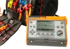
The MS-08, M4-16 and M1103 meters are specially designed to measure ground resistance.
Connection diagram of meter M416.
Resistance ground wires measured with an ohmmeter M372.
Touch voltage and current measurement. For measurements at a distance of 80 cm from the equipment, in places where the electric circuit can be closed through the human body, a metal plate 25x25 cm is placed on the surface of the ground or floor, simulating the resistance of the current that spreads from the human body. legs. The plate must be loaded with a mass of at least 50 kg. A measuring circuit consisting of an ammeter, a voltmeter and a resistor model of the resistance of the human body is assembled.
For the circuit, the ammeter should be selected with the lowest possible internal resistance and the voltmeter with the highest possible internal resistance (accuracy class — not less than 2.5). The resistance of the model resistor at a frequency of 50 Hz should be taken as 6.7 kΩ — when measuring for normal (emergency) mode of electrical installation, 1 kΩ — when exposed for 1 s and 6 kΩ — when exposed for more than 1 s for emergency mode of electrical installations with a voltage of up to 1000 V in each neutral mode and over 1000 V with isolated neutral, 1 kOhm — for emergency operation of electrical installations with voltages over 1000 V with an effectively grounded neutral… Resistance deviation should not exceed ± 10%.
After precautions have been taken, voltage can be applied to the case of the device under test. During the measurements, modes and conditions must be established that create the greatest contact voltages and currents affecting the human body.
Step voltage measurement. For measuring step voltage at the necessary distance from the fault in the ground with a distance of 80 cm from each other (along the length of the step), two metal plates with dimensions of 25x12.5 cm are placed. Each of these plates is loaded with a load of at least 25 kg. The measurements are performed in the same way as the touch voltage measurements.