Measurement of the resistance of the protective earth loop
Protective earthing is an intentional electrical connection to ground or the equivalent of non-conductive metal parts that may be energized by a short circuit to ground.
Task of protective grounding - eliminating the danger of electric shock in case of touching the casing and other non-current-carrying metal parts of the live electrical installation.
The principle of grounding is to reduce the voltage between the live box and the ground to a safe value.
Grounding devices after installation work and periodically at least once a year are tested according to the program of the Electrical Installation Code. The test program measures the resistance of the grounding device.
The resistance of the earthing device to which the neutrals of generators or transformers or the outputs of single-phase current sources are connected, at any time of the year should be no more than 2, 4, 8 ohms, respectively, at a line voltage of 660, 380 and 220 V on a three-phase current source or 380, 220 and 127 V single-phase current source.
Grounding device loop resistance measurements are made with an M416 or F4103-M1 grounding meter.
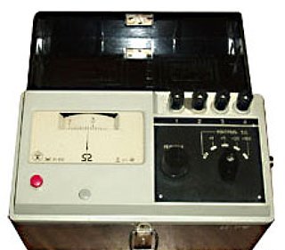
Description of the grounding device M416
The M416 earthing devices are designed to measure the resistance of earthing devices, active resistances and can be used to determine soil resistivity (?). The measurement range of the device is from 0.1 to 1000 ohms and there are four measurement ranges: 0.1 ... 10 ohms, 0.5 ... 50 ohms, 2.0 ... 200 ohms, 100 ... 1000 ohms. The power source is three 1.5 V dry galvanic cells connected in series.
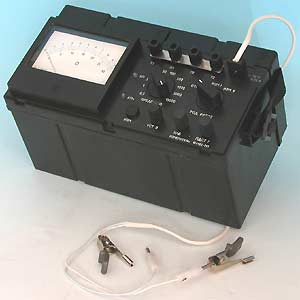
F4103-M1 grounding meter
The F4103-M1 earth resistance meter is designed to measure the resistance of earthing devices, soil resistance and active resistance both with and without interference in the measurement range of 0-0.3 Ohm to 0-15 Kom (10 ranges) .
The F4103 meter is safe.
When working with the meter in networks with a voltage of more than 36 V, it is necessary to comply with the safety requirements established for such networks. Accuracy class of the meter F4103 — 2.5 and 4 (depending on the measurement range).
Power supply - element (R20, RL20) 9 pcs. The frequency of the operating current is 265-310 Hz. The time to establish the operating mode is no more than 10 seconds. The time to establish the readings in the «MEASURE I» position is no more than 6 seconds, in the «MEASURED II» position — no more than 30 seconds. The duration of continuous operation is not limited. The average mean time between failures was 7,250 hours. Average service life — 10 years. Working conditions — from minus 25 ° C to plus 55 ° C. Overall dimensions, mm — 305x125x155. Weight, kg, no more — 2.2.
Before taking measurements with the F4103 meter, it is necessary, if possible, to reduce the number of factors that cause additional error, for example, to install the glucometer practically horizontally, away from strong electric fields, to use power supplies 12 ± 0, 25 V, the inductive component should only be considered for circuits whose resistance is less than 0.5 Ohm, interference detection, etc. Alternating current interference is detected by turning the needle when the PDST knob is turned to the «MEASURED» mode. Interference of a pulsed (spasmodic) nature and high-frequency radio interference is detected by constant non-periodic oscillations of the needle.
The procedure for measuring the resistance of the protective earth circuit
1. Insert the batteries into the meter.
2. Set the switch to «Control 5?»
3. Connect the connecting wires to the device as shown in Figure 1 if measurements are made with the M416 device or Figure 2 if measurements are made with the F4103-M1 device.
4. Deepen the additional auxiliary electrodes (ground electrode and probe) according to the diagram in fig. 1 and 2 at a depth of 0.5 m and connect the connecting wires to them.
5. Place the switch in position «X1».
6. Press the button and turn the «slidewire» knob to bring the indicator arrow to zero.
7. The measurement result is multiplied by a factor.
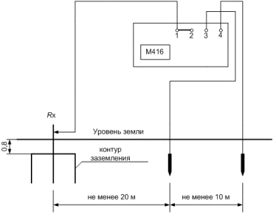
Connection of the M416 device for measuring the resistance of the earth loop
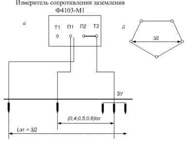
Connection of the device F4103 -M1 for measuring the resistance of the ground loop: a — connection diagram; b — contour of the earth