Galvanic installations — device, structures and use
Power supply units for galvanic installations.
 Rectifiers of thyristors or valves connected to a three-phase network of 380 V are used to power electroplating baths and machines for electrochemical processing of metals. electrolysis DC generators of suitable voltage can also be used.
In surgery for electroplating in small enterprises there are also galvanic installations with generators of the ND type for currents up to 5000 A. for a voltage of 6/12 V. Currently, such units are not produced.
Rectifiers of galvanic installations are classified according to the nominal rectified current and voltage and according to the parameters of the rectified current — irreversible, reversible and pulsed. The main types of power supply units for galvanic baths: TE, TEP, TV, TVR, TVI, VAK, VAKR for rated currents from 100 to 3200 A.
Thyristor blocks TE, TV provide automatic stabilization of rectified current or rectified voltage or current density. The range of current and voltage regulation is from 10 to 100% of nominal.
Reversible blocks TEP, TBR, VRKS allow you to get a bipolar rectified current at the output (that is, to change the direction of the current in the bath) with automatic repetition of the specified duration of the forward and reverse current. The duration of the forward polarity current setting is 2-200 s, the reverse is 0.2-20 s.
Reversible units also allow continuous operation with current of any polarity — no reversal.
Pulsed units (eg TVI) provide both pulsed and continuous output current. The duration of the pulse current is 0.01-0.1 s, the duration of the pauses between pulses is 0.03-0.5 s.
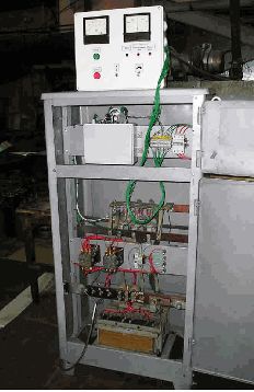
Electric rectifier
Rectifiers of galvanic installations have short-circuit protection on the AC and DC side, overload protection above 1.1 of the rated current and thyristor overheating protection.
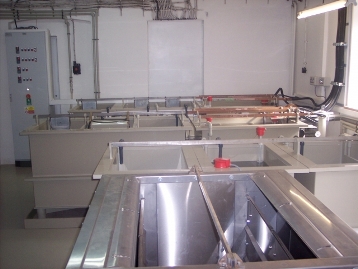
Rectifiers are mounted in cabinets and installed in closed, heated and ventilated industrial premises. The devices can be located in the immediate vicinity of the baths under conditions that exclude the penetration of electrolyte splashes.
Parallel and serial connection of blocks of galvanic installations is not allowed.
Power circuits for galvanic baths
The most common power supply scheme for galvanic baths is the power supply from its own rectifier, that is, individually. In this case, it is easiest to ensure optimal mode and automatic regulation of electrolytic processes, stabilization of current or voltage, reversal, etc., using automatic devices of the rectifier unit.
In low-power galvanic installations, a group supply scheme is used: a bus or bus leaves a direct current source, to which several baths are connected through their individual shields.
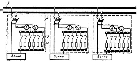
Group power scheme for galvanic baths: 1 — line from the power source, 2 — bath shield, 3 — switch, 4 — regulating resistance
Rheostats for galvanic baths
When several galvanic baths are powered by one common direct current source (rectifier, generator), it is impossible to maintain the required mode with the help of devices on the power supply unit. Adjustment is made individually for each bathroom.
Use for stepwise regulation of bath current rheostatslocated on the slab of each bathroom. Most often, the rheostat is implemented in 6 steps, which are turned on in parallel with each other and all together in series with the bath.
Rheostats are made of constantan, iron or nichrome wireentwined in a spiral. Each spiral section is switched on by its own single-pole switch. By including a different number of coils with switches, they regulate the current in the bath.
To reduce the heating of the contacts at the points of attachment of the spirals to the contact bolts of the switches, the end of the spiral is straightened to a length of 50-75 mm, so that the clear distance from the spiral to the plane of the shield is at least 50 mm.
Panels for galvanic installations
To control the operation of the baths, each of them should have an ammeter. If the technological process requires regulation of the bath voltage, a voltmeter is also installed on the shield. The measuring instruments are applied through a magnetoelectric system.
Devices, contact bolts for connecting current wires, rheostats and switches are mounted on shields located near the bathroom on corner steel racks.
The shields are made of 3 mm thick sheet steel with an anti-corrosion coating. The equipment is mounted on porcelain pads. The manufacture of marble shields is permitted. At the same time, to reduce hygroscopicity (moisture absorption) in damp rooms of electroplating workshops, the back surface of the shields should be painted with oil paint.