Induction oven circuits
 The article discusses the schemes of induction melting furnaces (channel and crucible) and induction hardening installations driven by machine and static frequency converters.
Diagram of a furnace with an induction channel
Almost all designs of industrial ducted induction furnaces are made with detachable induction blocks. The induction unit is an electric furnace transformer with a lined channel to accommodate molten metal. The induction unit consists of the following elements, housing, magnetic circuit, lining, inductor.
Induction units are produced as single-phase and two-phase (double) with one or two channels per inductor. The induction unit is connected to the secondary side (LV side) of the electric furnace transformer using contactors with arc suppression devices. Sometimes two contactors are included with supply contacts operating in parallel in the main circuit.
In fig. 1 shows a power supply diagram for a single-phase duct furnace induction unit. Overload relays PM1 and PM2 are used to control and stop the furnace in case of overload and short circuit.
Three-phase transformers are used to supply three-phase or two-phase furnaces that have either a common three-phase magnetic circuit or two or three separate core-type magnetic circuits.
Autotransformers are used to power the furnace during the metal refining period and to maintain an idle mode for more accurate power control during the metal finishing period to the desired chemical composition (with silent, no drilling, mode of melting) as well as regarding the initial furnace starts during the first melts which are carried out with a small volume of metal in the bath to ensure gradual drying and sintering of the lining. The power of the autotransformer is selected within 25-30% of the power of the main transformer.
In order to control the temperature of the water and air cooling of the inductor and the housing of the induction unit, electrocontact thermometers are installed, which give a signal when the temperature is exceeded. The furnace shuts off automatically when the furnace is turned to drain the metal. Limit switches connected to the electric furnace drive are used to control the position of the furnace. In furnaces and mixers with continuous operation, when the metal is drained and new parts of the charge are loaded, the induction units are not turned off.
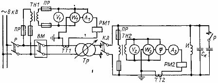
Rice. 1. Schematic diagram of the power supply of the induction unit of the channel furnace: VM - power switch, CL - contactor, Tr - transformer, C - capacitor bank, I - inductor, TN1, TN2 - voltage transformers, 777, TT2 - current transformers , R — disconnector, PR — fuses, PM1, PM2 — overcurrent relay.
To ensure reliable power supply during operation and in case of emergency, the drive motors of the induction furnace tilting mechanisms, the fan, the drive of the loading and unloading devices and the control system are powered by a separate auxiliary transformer.
Schematic of an induction crucible furnace
Industrial induction crucible furnaces with a capacity of more than 2 tons and a power of more than 1000 kW are powered by three-phase step-down transformers with secondary load voltage regulation connected to a high-voltage network with an industrial frequency.
The furnaces are single-phase, and in order to ensure uniform loading of the mains phases, a balancing device is connected to the secondary voltage circuit, consisting of a reactor L with inductance regulation by changing the air gap in the magnetic circuit and a capacitor group Cc connected to an inductor in triangular shape (see ARIS in Fig. 2). Power transformers with a capacity of 1000, 2500 and 6300 kV -A have 9 — 23 secondary voltage steps with automatic power control at the desired level.
Furnaces of smaller capacity and power are powered by single-phase transformers with a capacity of 400-2500 kV-A, with a power consumption of more than 1000 kW, balancing devices are also installed, but on the HV side of the power transformer. At a lower power of the furnace and supply from a high-voltage network of 6 or 10 kV, it is possible to abandon the balun, if the voltage fluctuations when turning on and off the furnace are within the permissible limits.
In fig. 2 shows the power supply circuit for an induction frequency induction furnace.Furnaces are equipped with ARIR electric mode regulators, which, within the specified limits, ensure maintenance of voltage, power Pp and cosfi by changing the number of voltage steps of the power transformer and connecting additional sections of the capacitor bank. Regulators and instruments are located in the control cabinets.
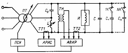
Rice. 2. Electric circuit of an induction crucible furnace from a power transformer with a balancing device and furnace mode regulators: PSN — voltage step switch, C — balancing capacitance, L — balun reactor, C -St — compensating capacitor bank, I — furnace inductor , ARIS — balancing device regulator, ARIR — mode regulator, 1K — NK — battery capacity control contactors, TT1, TT2 — current transformers.
In fig. 3 shows a schematic diagram of the supply of induction crucible furnaces from a medium frequency machine converter. Furnaces are equipped with automatic regulators of the electrical mode, an alarm system for "swallowing" the crucible (for high-temperature furnaces), as well as an alarm for a violation of cooling in the water-cooled elements of the installation.
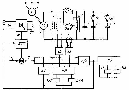
Rice. 3.Electric circuit of an induction crucible furnace from a machine medium frequency converter with a structural diagram of automatic adjustment of the melting mode: M — drive motor, G — medium frequency generator, 1K — NK — magnetic starters, TI — voltage transformer, TT — current transformer, IP — induction furnace, C — capacitors, DF — phase sensor, PU — switching device, UVR — phase regulator amplifier, 1KL, 2KL — line contactors, BS — comparison unit, BZ — protection block, OB — excitation coil, RN — voltage regulator.
Diagram of the induction hardening plant
In fig. 4 is a schematic diagram of the power supply of the induction hardening machine from a machine frequency converter. In addition to the power supply MG, the circuit includes a power contactor K, a quenching transformer TZ, on the secondary winding of which an inductor I is included, a compensating capacitor group CK, voltage and current transformers TN and 1TT, 2TT, measuring instruments (voltmeter V, wattmeter W , phasor) and ammeters of generator current and excitation current, as well as overcurrent relays 1RM, 2RM to protect the power supply from short circuit and overload.
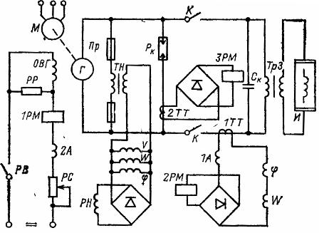
Rice. 4. Schematic diagram of an induction hardening unit: M — drive motor, G — generator, VT, TT — voltage and current transformers, K — contactor, 1PM, 2PM, ЗРМ — current relay, Pk — arrester, A, V , W — measuring devices, ТЗ — quenching transformer, ОВГ — generator excitation coil, РП — discharge resistor, РВ — contacts of excitation relay, PC — adjustable resistance.
To power old induction plants for heat treatment of parts, frequency converters of electric machines are used - a drive motor of synchronous or asynchronous type and a medium frequency generator of inductor type, in new induction plants - static frequency converters.
A diagram of an industrial thyristor frequency converter for powering an induction hardening unit is shown in fig. 5. The circuit of a thyristor frequency converter consists of a rectifier, a choke block, a converter (inverter), control circuits and auxiliary blocks (reactors, heat exchangers, etc.). According to the method of excitation, inverters are made with independent excitation (from the main generator) and with self-excitation.
Thyristor converters can operate stably both with a change in frequency over a wide range (with a self-adjusting oscillating circuit in accordance with changing load parameters) and at a constant frequency with a wide range of changes in load parameters due to a change in the active resistance of the heated metal and its magnetic properties (for ferromagnetic parts).
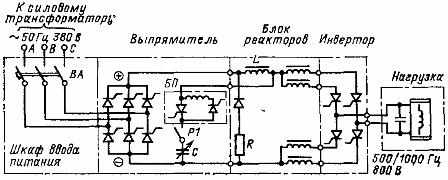
Rice. 5. Schematic diagram of power circuits of thyristor converter type TFC -800-1: L — smoothing reactor, BP — starting block, VA — circuit breaker.
The advantages of thyristor converters are the absence of rotating masses, low load on the base and little effect of the power factor on the reduction of efficiency, the efficiency is 92 - 94% at full load, and at 0.25 it decreases by only 1 - 2%.Also, since the frequency can be easily varied within a certain range, there is no need to adjust the capacitance to compensate for the reactive power of the oscillating circuit.