Main and distribution busbars
The busbar is a factory-made solid conductor for voltages up to 1 kV, supplied in whole sections.
In the shops of enterprises, where flocks and mechanisms are located throughout the area in rows and often move due to changes in the production process, trunk and distribution closed bus ducts are used as supply main lines and distribution network.
The advantages of tires
The main advantages of tires are:
a) saving non-ferrous metals in the backbone and distribution network,
b) high-speed assembly,
c) flexibility at work,
d) simplicity and reliability of verification under operating conditions.
Classification of tires
By design, the rails can be open, protected and closed.
Open bus ducts are used for trunk networks in rooms with normal environments. Open rails include open tap rails and trolleys.
They are made with aluminum tires placed along insulators attached to the trusses and columns of the workshop, respecting the norms of minimum heights and the smallest distance to pipelines and technological equipment.In industrial premises, the rails are placed at a height of at least 3.5 m from the floor level and at least 2.5 m from the overhead crane deck. The passage of open busbars through ceilings, walls and partitions is carried out in openings or insulating plates. In places that are dangerous due to the possibility of contact, open busbars are covered with metal nets or boxes.
Shielded and closed bus channels are the main type of networks used for internal power distribution.
In shielded busbars, the busbars are surrounded by a net, a box of perforated sheets, etc., to prevent accidental contact with the busbars and the penetration of foreign objects onto them. With closed busbars, the busbars are covered with a solid box.
The protected bus ducts are installed at a height of at least 2.5 m from the floor. Closed rails can be installed at any height. This is very convenient when installing electrical networks in the shop, since the bus can be laid along the line of machines at a height of 0.5 — 1 m. This reduces the length of the branches from the bus to the machine.
By purpose, the bus channels are trunk and distribution.
Busbars
Trunk lines are designed for high currents (1600 — 4000 A) and for several branch connections to them for powering consumers (two places every 6 m).
Distribution busbars
Distribution busbars are designed for currents up to 630 A and a large number of places (3 — 6) on a three-meter section for connecting electrical consumers.
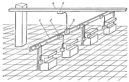 Installation of distribution bus in the workshop: 1 — straight section; 2 — junction box; 3 — input box; 4 — main bus; 5 — splitter of the main bus.
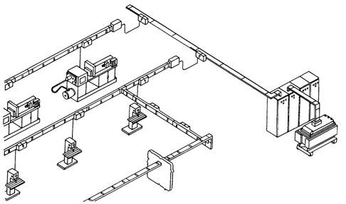
In the shops of industrial enterprises, closed distribution bus ducts are widely used.They are manufactured in factories and supplied in the form of a set of straight sections - sections (length of straight section 3 m) equipped with transition elements for connecting a number of sections in series, junction devices (junction boxes), as well as input boxes that connect the bus channels to the power network.

Bus junction boxes
Bus junction boxes are designed to connect machines and mechanisms. They are equipped with circuit breakers or fuses. Electrical receivers are connected to the busbar using junction boxes with plug contacts (without removing the voltage from the busbar) or bolted connections. Accordingly, the busbars are called plug-in or blind busbars. The most common are the attachment rails.
Branching from the rails to the production machines is done in thin-walled steel pipes. The rails are attached to trusses, hung on hangers to the building structures of the workshop or mounted on racks.
Typical full bus channels of the ShMA-73 series are produced for memorial currents of 1600, 2500 and 4000 A with a voltage of up to -1000 V, and distribution built-in bus channels of the ShRA-73 series - for currents of 250, 400 and 630 A with a voltage of up to 380 V.

Main bus channels ШМА
The main bus channels of the ShMA type in a protected design have three buses. The bus bar zero is two aluminum angles located outside the housing and used to secure the bus channel. Each phase of the SMA busbar is made of two insulated aluminum bars with a rectangular cross-section.
The main SMA busbar is completed by straight sections with lengths of 0.75, 1.5, 3 and 3.5 m, corner, triple, branch, connecting and assembly sections.In addition, special sections are performed: flexible — to avoid obstacles and phases — to change the phase rotation. The main type of SHMA bus sections is a straight line with a length of 3 m. A bus of any complexity is completed by a set of sections. Tires of adjacent sections are connected by welding or a special bracket with one bolt. They aim to fill the largest number of rail sections by welding.
It has an upgraded ShMA busbar design that has four busbars located inside the body — three phases and one neutral.
SHMAD DC main busbars are used for DC mains and rolling machine main drive buses.
SHRA Distribution Busbars
ShRA distribution channels consist of straight sections 3 m long and corner sections.

Elements (sections) of the channel of the distribution bus 1 — a plug covering the place of spare connection, 2 — a junction box with fuses, 3 — a junction box with an automatic switch (switch handle is visible), 4 — a box with signal lamps indicating the presence of voltage, 5 — input box
The figure shows a general view of the busbar distribution bus of the ShRA-73 series (four-wire).
All four busbars (three-phase conductors and neutral) are made of bare aluminum bars with a rectangular cross-section. The cross-sections of the phase and neutral wires are the same. The busbars of the busbar sections are bolted together. Each straight 3m section has eight pin windows for connecting junction boxes. The distance between the junction boxes is 1 m. The junction box is equipped with an AE20 or A37 circuit breaker or PN2 fuses for a rated current of 100 A.
There are also distribution four-wire SHRM busbars with 100 A AC copper busbars rated at 380/220 V. ShRM busbars provide connections for both three-phase and single-phase electrical receivers, including power lamps.
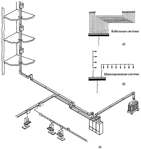
The use of busbars: a — example of a cable network, b — example of a network of busbars, c — laying of busbars
Application of busbars
SCO Lighting Busbars
Lighting conduits for 25 A, 380/220 V, type SHOS — four-core, with round insulated conductors 6 mm2. The length of the SCO busbar trunking sections is 3 m. The section has six single-phase plug connections (phase-neutral) every 0.5 m. The SCO busbar trunkings are available with 10 A plugs, right angle, flexible and inlet sections. Using a set of these elements, a complete rail channel is selected for routes of any complexity. Adjacent sections of the rails are connected by a joint with additional fastening with two screws.
Luminaires are suspended directly from the SCO busbar using a hook clamp and attached to each plug connection. The maximum distance between the fixing points is 2 m. In cases where the luminaires are not mounted on busbar boxes, the SHOS67 busbar fixing step can be increased to 3 m.