Determination of the estimated loads of the city's electrical network
 The calculation of the loads of the city network includes the determination of the loads of individual users (residential buildings, public buildings, communal services, etc.) and elements of the power supply system (distribution lines, transformer substations, distribution points, energy centers, etc. ).
In fig. 1 shows a simplified diagram of a section of a city network, and in fig. 2 gives an algorithm for determining design loads, its elements (without taking into account power losses in lines and transformers) and explanations for the implementation of individual points of the algorithm.
If, in addition to the loads of the urban network, the source feeds industrial enterprises or agricultural areas, then all the loads of the buses of this source are summed up, taking into account the maximum alignment factor.
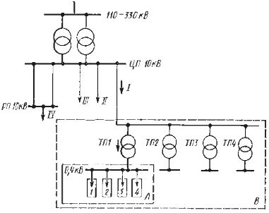
Rice. 1. A possible diagram of the section of the urban grid: CPU — power center, RP — distribution point, TP — transformer substation.
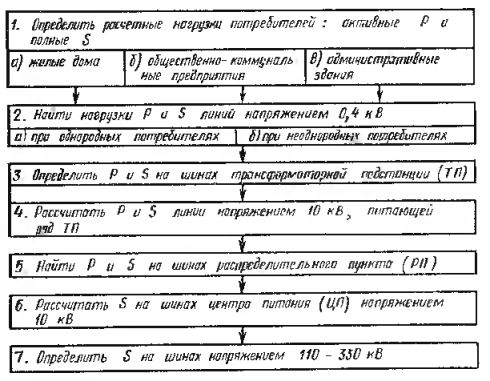
Rice. 2.Algorithm for determining the loads of a section of a city network
Explanations for the implementation of the algorithm shown in Fig. 2.
1a. Active load of a residential building (apartments and energy consumers) is defined as
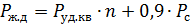
where Square meter - specific load of apartments, depending on the type of kitchen stoves and the number of apartments (n) in the house; Pc — load of energy consumers at home.
In turn
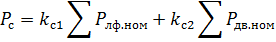
where kc1 and kc2 — respectively, the demand coefficients for installations of elevators and other electric motors (fans, water supply pumps, etc.), kc2 taken equal to 0.7;
Plf.nom and P.dv.nom — nominal power of the elevator motor and other electric motors (according to passport data);
Full load of a residential building and its power line

where cosφ The power factor of the line supplying the residential building.
1b and 1c. Active loads from utilities and administrative buildings in rough calculations are convenient to determine from the aggregated specific loads, depending on their performance indicators:

where P.pond — the specific design load per unit of production indicator (workplace, seat, square meter of commercial area, bed, etc.);
M — production indicator characterizing the productivity of the enterprise, the volume of production, etc.
Full loads from the considered enterprises and buildings are taken into account cosφ... If necessary, more accurate calculations can be made based on individual projects of the internal electrical equipment of the considered objects and according to the current method of determining their loads.
Electrical loads communal services (boilers, water supply, sewage), as well as intra-city electrified transport are determined by special methods.
2a. Active load on a 0.4 kV line, feeder group of similar residential buildings (homogeneous consumers)
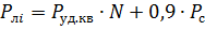
where P.be sq. —specific load of apartments, depending on the type of kitchen stoves and the number of apartmentsN fed by one line.
Full load on the line, the supply of homogeneous consumers is determined by taking into account their cosφ.
2b. Active load on a 0.4 kV line supplying heterogeneous users (residential buildings with different types of stoves, utilities, office buildings, etc.):
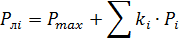
where Pmax is the largest of the loads supplied by the line (the load forms a maximum); ki — coefficients of combination, taking into account the discrepancy between the maximum loads of individual users relative to Pmax; Pi — other load lines.
A full load on a line supplying heterogeneous consumers with different cosφ can be simplified as
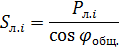
Here cosφtotal does the total power factor correspond to the total reactive load factor:
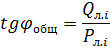
where Ql.i is the total reactive load of the line, determined taking into account individual users.
3. Active and full load of the transformer substation are defined similarly to points 2a and 2b, but all users of the given TP are taken into account. The resulting load is considered reduced to 0.4 kV busbars substation.
4. Active load on the 10 kV line feeding a number of transformer substations:

where kTP1 — the coefficient of combining the maximum loads of the transformer substation; PTPΣ- total load of individual transformer substations connected to the line.
Full load lines with a voltage of 10 kV is determined by taking into account the power factor during the period of maximum load, assumed equal to 0.92 (corresponds to natgφ = 0.43).
5. Active and full tire loads at the distribution point (RP) are defined similarly to item 4, but all TPs applied to this RP are taken into account.
6. Expected bus load of the power plant (CPU) with a voltage of 10 kV is determined by taking into account the discrepancy of the maximum loads of users of urban networks, industrial enterprises and others by multiplying the sum of their loads by the combination factor of the maxima kmax1 or kmax2.
7. Load on buses with a voltage of 110-330 kV if there are double-winding transformers 110-330 / 10 kV in the substation, the load is on the busbars of the 10 kV processor. For three-winding transformers, the additional load on the third winding must be taken into account.