Differential protection of the longitudinal line
 Longitudinal differential zProtection is based on the principle of comparing the values and phases of the currents at the beginning and end of the line. For this purpose, the secondary windings of the current transformers on both sides of the line are interconnected by wires as shown in fig. 1. These wires continuously circulate secondary currents I1 and I2. To perform differential protection, a PT differential relay is connected in parallel with the current transformers. The current in the coil of this relay will always be equal to the geometric sum of the currents coming from the two current transformers

If the transformation ratios of the current transformers TT1 and TT2 are the same, then during normal operation, as well as an external short circuit (point K1 in Fig. 1, a), the secondary currents are equal in value I1 = I2, directed oppositely to the relay .
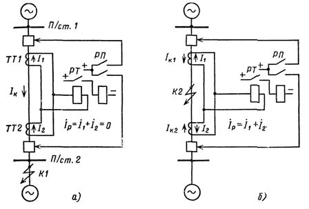
Rice. 1. The principle of implementation of longitudinal differential protection of the line and passage of current in the relay with an external short circuit (a) and with a short circuit in the protected area (b)
Relay current

and the relay does not turn on.
In the event of a short circuit in the protected area (point K2 in Fig.1, b) the secondary currents in the relay winding will match in phase. And therefore it will be generalized

If

the relay will pick up and trip the breakers.
In this way, the differential longitudinal protection with constantly circulating currents in the relay coil reacts to the total short-circuit current in the protected area (the line section between current transformers TT1 and TT2) while providing instantaneous tripping of the damaged line
The practical application of differential protection schemes required the introduction of a number of structural elements due to the peculiarities of the operation of these protections on the lines of power systems.
First, in order to turn off the long lines on both sides, it turned out to be necessary to connect two relays according to the differential scheme: one at substation 1, the other at substation 2 (Fig. 2).
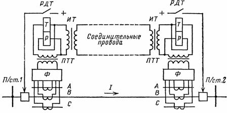
Rice. 2. Schematic diagram of the longitudinal differential protection of the line: Ф — direct and negative sequence current filters; PTT — intermediate current transformer; IT — isolation transformer; RTD — differential relay with stop; P — working and T — brake coil of the relay
The connection of two relays led to an uneven distribution of secondary currents between the relays (the currents were distributed inversely proportional to the resistances of the circuits), the appearance of an imbalance current and a decrease in the sensitivity of the protection.
Note also that this unbalance current sums in the relay with an unbalance current caused by a mismatch in the magnetizing characteristics and some difference in the transformation ratios of the current transformers.In order to adjust from unbalance currents in protection, not simple differential relays were used, but differential relays with RTD stop, which have greater sensitivity.
Secondly, the connecting wires with their considerable length have a resistance that is many times higher than the load resistance allowed for current transformers. To reduce the load, intermediate PTT current transformers with a transformation ratio n were used, with the help of which the current circulating through the wires was reduced by n times and thus the load from the connecting wires was reduced by n2 times (the value of the load is proportional to the square of the current).
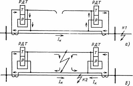
Rice. 3. Passage of current in the relay coils in case of breakage (a) and short circuit of the connecting wires (b): K1 — short circuit point; K2 — short circuit point in the protected area
Isolation transformers were also provided in the longitudinal differential protection scheme to separate the connecting wires from the relay circuits and protect the latter from high voltages induced in the connecting wires during the passage of the short-circuit current conductor.
Longitudinal differential protection of the DZL type, widely distributed in electrical networks, is built on the principles set out above and contains the elements indicated in fig. 2. The presence of connecting wires in the secondary circuits of DLP limits the area of its application to lines of short length (10-15 km).
Checking the serviceability of the connecting wires.
During operation, damage to the connecting wires is possible: breaks, short circuit between them, short circuit of one of the wires to ground.
In the event of a break in the connecting wire (Fig. 3, a), the current in the working and braking coils of the relay becomes the same, and the protection may work incorrectly in the case of a through short circuit and even with a load current (depending on the value of Isc ).
A short circuit between the connecting wires (Fig. 3, b) bypasses the relay windings, and then the protection may not work in the event of a short circuit in the protected area.
For timely detection of damage, the serviceability of the connecting wires is monitored by a special device. The control is based on the fact that a rectified direct current is superimposed on the operating alternating current circulating in the connecting wires when they are in good condition, which does not affect the operation of the protection.
Rectified voltage is supplied to the connecting wires only in one of the substations, where the control unit has a rectifier, which in turn receives power from the voltage transformer of the active bus system. The connection of the control device to one or another bus system is carried out through auxiliary contacts of bus disconnectors or relay repeaters of bus disconnectors of the protected line.
In the event of a break in the connecting wires, the direct current disappears and the control device signals a fault, removing the operating current from the protection of both substations.When the connecting wires are closed together, it gives a signal and removes the protection from action, but only on one side - the side of the substation where there is no rectifier. In the case of a decrease in the insulation resistance of one of the connecting wires to the ground (below 15-20 kOhm), the control device also gives the corresponding signal.
If the connecting wires are in good condition, the monitoring current passing through them does not exceed 5-6 mA at a voltage of 80 V. These values should be periodically checked by the service personnel in accordance with the operating instructions of the protection.
Operating personnel must remember that before any type of work is permitted on the connecting wires, it is necessary to turn off the longitudinal differential protection, the connecting wire monitoring device and the starting of the backup device in the event of a circuit breaker failure. protection damage guards on both sides.
After finishing the work on the connecting wires, check their operability. For this purpose, the control device is included in the substation, where there is no rectifier. In this case, a fault signal should appear. The control unit is then switched on at another substation (corrected voltage is supplied to the connecting wires) and checked for a fault signal. The protection and tripping circuit of the circuit breaker failure protection device is activated when the connecting wires are in good condition.