Differential bus current protection
 The residual current busbar protection is designed to quickly disconnect the electrical circuits connected to the busbars in the event of a short circuit in the busbars or any other equipment included in the protection zone.
The area of its action is limited by the current transformers to which the protective relays are connected. The basis for applying the protection is the principle of comparing the values and phases of the currents of the electric circuits during short circuit and other modes of operation.
To implement the protection, the differential relay RT is connected to the current transformers of the links as shown in fig. 1. In this connection, the current in the relay will always be equal to the geometric sum of the secondary currents of the connections.
In case of a short circuit of the busbars (Fig. 1, a) the secondary currents of the links will have one direction and the sum of these currents will pass through the relay

If IR
With an external short circuit (Fig. 1, b), the current in the relay coil

the relay will not operate if it is set by the unbalance current due to the fault of the current transformers.
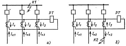
Rice. 1.Currents in the bus differential current protection relay in case of bus short circuit (a) and external short circuit (b)
Based on a general principle, the protection of the differential busbars can differ from each other according to the scheme, which is related to their adaptation to one or another main scheme of a substation. Bus differential protections are in effect for substations with one and two bus systems, as well as for substations with reactive lines and multiple feeders.
Differential current protection for substations with two bus systems with fixed connection distribution, which is often used as one of the means of limiting short-circuit currents in 110-220 kV networks, is of greatest interest from the point of view of their maintenance by operational staff. One of these defenses is discussed below.
A distinctive feature of the protection (Fig. 2) is the selectivity in disconnection of the damaged busbar system, if the established distribution of connections on the busbars is observed. The selectivity of action is provided by the use of the circuit of two selective current devices (sets of relays) PT1 and PT2 and a common starting element (set of relays) RTZ.
The relays of each selective set are connected to the current transformers of the sections fixed behind the given busbar system and act when the switches of those sections are actuated only. The relays of the common starter set are connected to the current transformers of the compartments of both the busbar systems and therefore operate in the event of a short circuit in either of the busbar systems. They do not respond to external short circuits, even if the fixing of the connections is broken.
The operation of the differential current protection of buses.
In the event of a short circuit on one of the bus systems, the current relays of the RTZ common starter set will operate and supply the operating current to trip the bus switch (relay RPZ) and simultaneously with the current relays of selection sets PT1 and PT2. The breaking of the connecting switches of the damaged bus system will occur as a result of the actuation of the intermediate relay of the relevant selector set.
In the event of a violation of the established connection fixation, the two sets of selective protection can be triggered by an external short circuit, since the currents in them are not balanced. However, this will not break the connections because the direct current is fed to the selector relay through a common starter kit, in which relay the currents will be balanced and it will not operate.
If, in the event of a broken fixing of the links, a short circuit occurs on one of the operating bus systems, then all three sets of protection will operate and both bus systems will trip. In order to preserve the selectivity of the protective action in the event of a change in the fixing of the connections, it is necessary to switch from one selective set to another current and operational circuits of the connections transferred to another operating bus system.
The protection circuit (Fig. 2) provides a link-fixing switch that shunts the DC circuits of the two selectors. By turning on this switch, the contacts of the current relays PT1 and PT2 of the selector sets are disconnected from the protective circuit, the switch is turned on before starting work with switching devices that violate the established fixing of connections.It should also be on when a bus system is running and all connections are on.
When the circuit breaker is turned on, the protection acts to turn off all the switches at once. If the circuit breaker is switched on when both bus systems are operating and the connection distribution is fixed, then in the event of a short circuit on one of the bus systems, the protection will act non-selectively to disconnect the circuit breakers of both bus systems directly from the common set.
In order to check the voltage of one of the bus systems using ShSV, the protection circuit provides an automatic blocking which delays the tripping of the circuit breakers for the connections of the working bus system in the event that the ShSV is short-circuited. Blocking is done using the PV7 relay, which has a longer return delay time than the ShSV trip time. At this time, relay RP4 removes the negative operating current from relays RP1 and RP2 of the selective sets, so they will not be able to close the tie switches. The ShSV shutdown pulse is supplied without delay from the RPZ relay as soon as the starter kit relay is activated. If, for any reason, the tripping of the SHSV is delayed, after the return time of the PV7 relay has expired, the operating bus system will shut down.
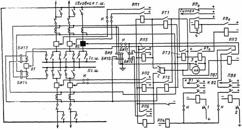
Rice. 2. Schematic diagram of the differential current protection of a double-bus system: 1 — control switch of the connecting bus switch B1 (ШСВ); 2 — the same bypass switch B2 (OB).Contacts 1 and 2 are closed only for the time of switching on, in the figure they are conditionally depicted as buttons; 3 — button for maneuvering the milliammeter; 4 — button for unlocking the signal relay; PT1 — current relay of selective set I, bus system; PT2 — same bus system II; RTZ — current relay from the general set; PT0 — current relay of the signal set; RP1 — RP6 — intermediate relays; PR0 — the same set of signals: PV7, PV8 — intermediate relays with a time delay; РБ0 — signal time relay; BI9 -BI14 — test blocks; C — breaker of fixation violation; H — pads (shutdown devices)
A similar blocking (relay PV8) is provided in case of testing the system voltage on the bypass bus using the bypass switch. During the test, the secondary circuits of the current transformers of the bypass switch must be removed from the protective circuit (the covers of the test units BI9 and BI10 are removed). Otherwise, any short circuit in the bypass bus system will be an external short circuit and the protection will not work.
During operation, interruptions or maneuvering of the secondary circuits of the current transformers to which the protective relays are connected are not excluded. As a result, the balance of currents in the relay is disturbed and they can work even during the normal operation of the substation.
To prevent incorrect operation of the protection, a device is provided for monitoring the state of the current circuits, made using a current relay PT0 and a milliammeter mA, included in the neutral wire of current transformers.At a certain (dangerous) value of the unbalance current, the control device is triggered, disables the protection and notifies the personnel of the malfunction. Gradually developing faults in the current circuits are revealed by periodic measurements of the unbalance current using a milliammeter by pressing button 3, bypassing it.