Electrical schemes for auxiliary needs of substations 35-220 kV
 At electric substations 35-220 kV and higher, for the power supply of auxiliary mechanisms, aggregates and other consumers with their own needs (s. N.), more recently developed electrical schemes are used.
The main users own transformer substations are:
• working circuits with alternating and rectified current,
• cooling system for transformers (autotransformers),
• on-load voltage regulation devices (OLTC),
• system for cooling and lubrication of bearings of synchronous compensators (SK),
• hydrogen installations,
• devices for charging and recharging batteries,
• lighting (emergency, internal, external, security),
• communication and telemechanical devices,
• pumping units (fire extinguishing, household, technical water supply),
• compressor installations and their automation for air switches and other purposes,
• electric heating devices for battery rooms, switches, disconnectors and their drives, receivers, distribution devices, various external cabinets,
• boiler room, stills, ventilation, etc.
 Cut off power to such users own needs transformer substationssuch as cooling transformers and synchronous compensators (SK), oil pumps, lubrication of SK bearings, communication and telemechanical devices, fire pumps, can cause disruption to the normal operation of the substation.
Therefore, when choosing electrical connection schemes for auxiliary needs of substations, measures are provided to increase their reliability: installation at a substation of at least two transformers of own needs (usually no more than 560 or 630 kVA), section of a bus of own needs. NS Application of automatic transfer switch (ATS) on the sectional switch, redundancy on the high voltage side (s. N.) etc.
In fig. 1. diagrams of own needs used substations depending on the type of operating current are shown. With alternating and rectified current, a circuit is recommended (Fig. 1, a), according to which direct connection of self-needs transformers to the low-voltage windings of the main transformers (autotransformers) is provided.
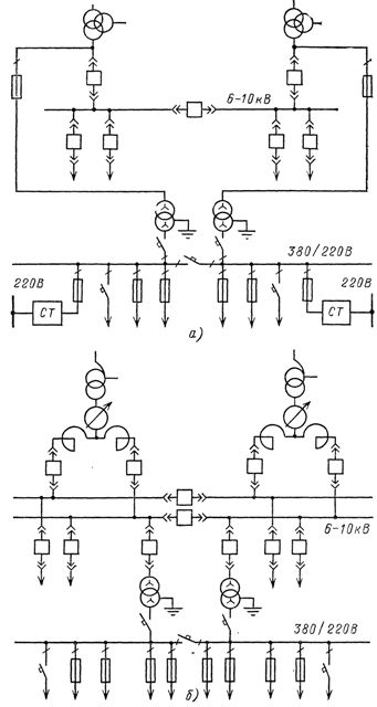
Rice. 1. Schemes for connecting auxiliary devices in the presence of substations: a — alternating and rectified operating current, b — direct operating current
This connection provides auxiliary power supply and circuit breaker operations at 6-10 kV busbars. At constant operating current, the circuit shown in Fig. 2.3, b, when transformers are directly connected to 6-10 kV buses.
Usually one or two operational transformers are installed at substations. own needs, but in the presence of particularly critical users, a spare transformer own needs can be provided.For example, in fig. 2. shows a diagram for a 220 kV substation with three self-demand transformers, one of which is redundant with an independent supply from a neighboring substation.
More complex schemes are used, for example, in 500 kV substations and the like. This is due to the fact that often on outdoor switchgear in auxiliary buildings, together with SC excitation devices, SC relay protection and control panels, AT, the 220 and 500 kV connections are also switchboards from which the management of the 0.4 kV connections serving these facilities is carried out.
Rice. 2. Simplified diagram of own needs substations 220 kV
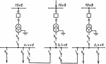
In fig. 3 shows a simplified diagram of own needs of a 500 kV substation. It has several shields of its own needs: 220 kV external switchgear, 500 kV external switchgear, main control, pumping station, transformer oil facilities (TMH). All these shields are connected by jumpers and are mutually protected. Two transformers are connected to their autotransformers and the third (spare) to the nearby transformer station (TP) of the city cable network.
In fig. 3 connections in cross-section and jumpers (made using switches and circuit breakers) designed for automatic transfer of reserve in case of voltage interruption are equipped with appropriate automation devices from the 6-10 kV side and circuit breakers on the 0.4 kV side. In the same figures, the arrows tentatively indicate the connections with 0.4 kV.
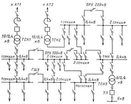
Rice. 3. Simplified diagram of own needs substations 500 kV
Currently, these switches are also typically used on output boards with linear connections.Temperature sensors and magnetic starters are installed on some of them, which serve to automatically turn on and off the heating devices (in KRUN and other places) depending on the outside temperature.
In some cases, fuses and circuit breakers are installed instead of breakers on low-responsibility connections for own needs (workshops, oil purification plants).
To improve reliability and uniform charging of transformers own needs, electrical receivers that ensure the normal operation of the main electrical equipment of the substation (cooling of transformers and SC, heating of tanks for circuit breakers, compressor, etc.) are fed from two bus sections .