Electric clamps - types, principle of operation, use
 Electric clamp intended for measuring electrical quantities — current, voltage, power, phase angle, etc. — without interrupting the current circuit and without disturbing its operation. According to the measured values, there are clamp ammeters, ammeters, voltmeters, wattmeters and phase meters.
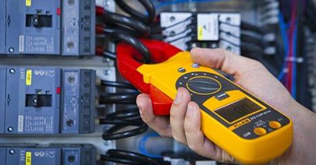
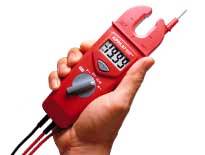
The most common are AC ammeters, which are usually called a clamp meter... They are used to quickly measure the current in a wire without interruption and without shutting it down. The clamps are used in installations up to and including 10 kV.
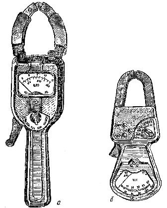
The simplest alternating current clamp works on the principle of a single-turn current transformer, the primary winding of which is a bus or wire with a measured current, and the secondary multi-turn winding, to which the ammeter is connected, is wound on a split magnetic circuit ( Fig. 1, a) .
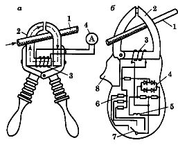
Rice. 1.Circuits of an alternating current meter: a — a circuit of the simplest bracket using the principle of a single-turn current transformer, b — a circuit combining a single-turn current transformer with a rectifier device, 1 — a wire with a measured current, 2 — a split magnetic circuit, 3 — secondary winding, 4 — rectifier, 5 — measuring device frame, 6 — shunt resistor, 7 — measuring limit switch, 8 — lever
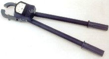
To wrap around the busbar, the magnetic circuit opens like conventional pliers when the operator acts on the insulating handles or levers of the pliers.
Modern clamp meter design uses a circuit that combines a current transformer with a rectifier. In this case, the terminals of the secondary winding are connected to the electrical measuring device not directly, but through a set of shunts (Fig. 1, b).
The clamps are of two types: one-handed for installations up to 1000 V and two-handed for installations from 2 to 10 kV inclusive.
Electric clamping pliers have three main parts: working, which includes a magnetic circuit, windings and a measuring device, insulating - from the working part to the limiter, handle - from the limiter to the end of the pliers.
In single-handed pliers, the insulating part also serves as a handle. Opening the magnetic circuit is done using a pressure lever.
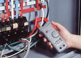
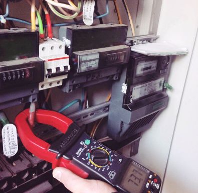
Rules for using ticks. The scobometer can be used in closed electrical installations, as well as in open ones in dry weather. Clamp measurements can be performed both on parts covered with insulation (wire, cable, tube fuse holder, etc.) and on bare parts (tires, etc.).
The person performing the measurement must wear dielectric gloves and stand on an insulating base. The second person should stand behind and slightly to the side of the operator and read the instrument readings on the electrical clamp.
Ts20 type clamp meter with sliding magnetic circuit and device rectifier refers to measuring current transformers. These clamps allow, when the magnetic circuit covers a wire with an alternating current with a frequency of 50 Hz, to measure a current in the range of 0 to 600 A. an electrical measuring device is switched on.
The current measured by the device is directly proportional to the current in the wire surrounded by the clamps and is measured on a scale graduated from 0 to 15 if the clamp switch is set to 15, 30 or 75 A or on the lower scale graduated from 0 to 300 when this switch is in position 300 (300 A).
Clamps of type Ts20 also allow you to measure alternating voltage up to 600 V, 50 Hz, for which their clamps are connected by wires to those points of the electrical circuit between which the voltage is measured, and the lever switch is placed in Position 600 V, where the secondary winding of the current transformer is short-circuited …
Measuring clamp: a — current, b — power
Measuring clamp type D90 with sliding ferrimagnetic magnetic circuit and ferrodynamic device make it possible to measure active power without breaking the current circuit by covering the wire with current and connecting the device with two wires with plugs to the mains voltage.
The clamps are designed to measure at two rated voltages — 220 and 380 V and a frequency of 50 Hz and respectively three rated currents — 150, 300, 400 A or 150, 300, 500 A, which will give a rated power factor Cos? =0.8 corresponding nominal active power measurement limits: 25, 50, 75 kW and 50, 100, 150 kW.
The readings in the measurement range 25, 50, 100 kW are made on the upper scale from 0 — 50, and in the limits of 75, 150 kW — on the lower traverse 0 — 150. The voltage switching is made with plugs, one of which is inserted in the socket of the generator marked «*»: And the other in a socket marked 220 or 380 V.
The switching of the current measurement limits is done with a toggle switch, which is set to one of six positions corresponding to the values of the nominal line voltage and the nominal value of the measured active power.
The clamp meter type D90 can measure active power in three-phase circuits, which requires the line conductor to be covered with a magnetic circuit and the voltage coil to be connected to the corresponding line or phase voltage. In the symmetrical mode, it is enough to measure the power of one phase and multiply the measurement result by three, and in the asymmetrical mode, measure the respective powers one by one according to the diagrams of two or three devices and add the results algebraically.
The measurement error when using electrical measuring clamps of types C20 and D90 does not exceed 4% of this measurement limit at any position of the clamps themselves and of the wire in the window of the magnetic circuit.