Control cables in electrical installations — purpose, types of construction, application
Cable products in electrical networks are used to transmit electricity over a distance. They are used as direct power lines of energy flows or for the operation of circuits in control, protection, automation, signaling systems.
Power cables mainly work with high-voltage currents up to 35, 110 kV and more, or in a network of 0.4 kV. They are specially designed and manufactured for a specific type of voltage. Reference models are used for other purposes.
Purpose of control cables
It is connected not to power chains, but to their service systems, in which no increased power is transmitted. Their maximum operating voltage is usually limited to 380 or in some cases 1000 volts.
This provision helps to understand the division of electrical substation equipment into:
-
primary power circuits;
-
secondary service chains.
For example, in the switchgear of a 110 kV substation, all power equipment belongs to a primary loop that directly distributes, receives and transmits electrical energy.
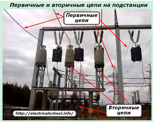
The secondary circuits are connected to current and voltage measuring transformers to take into account the processes taking place in the primary circuit, as well as to solenoids and control coils of power switches, their auxiliary contacts and repeaters of disconnectors, separators and other devices.
All secondary equipment is connected to each other in electrical circuits through cables that are located on the surface of building structures, in special cable trays and channels, in the ground or outdoors.
These cables are named control... Explains their purpose — providing control of technological process algorithms occurring in the primary loop.
With the help of control cables, electrical signals are transmitted through circuits:
-
measurements of the main parameters of electrical energy;
-
control of power circuit equipment,
-
automation and protection of the electrical system;
-
other devices serving basic equipment.
How control cables are used
The photo below shows the termination of the control cable end from the terminal box of a 330 kV HV instrument transformer.
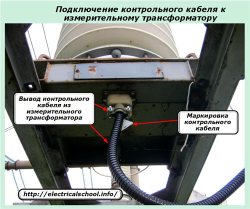
To protect it from the influence of the environment, metal tape and corrugated pipe are used. All control cables running in existing electrical installations are marked with special labels and signed in indelible ink. This greatly facilitates work and the search for possible malfunctions during operation.
On the reverse side, control cables are installed in distribution terminals, boxes, boxes, as shown in the following photo for 330 kV equipment.
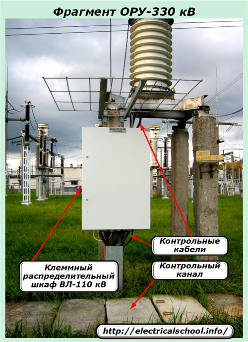
The same principle is observed in circuits with other voltages, for example 110 kV.
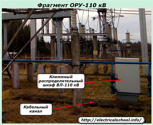
Control cables from the main power supply equipment are laid through special trays or channels, feed their circuits to terminal nodes, which ensure reliable operation of the circuit outdoors in all weather conditions.
After assembling the electrical circuits to the terminals of the distribution cabinets, the following control cables are again used, leaving directly on the panels in accordance with the scheme and project.
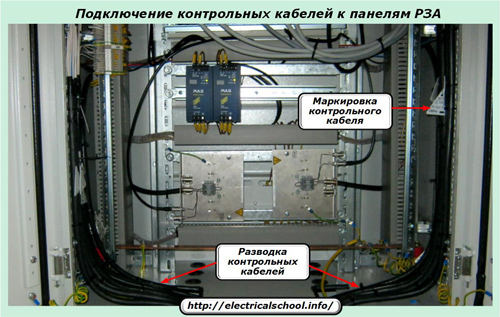
A variant of their connection to the panels for relay protection and automation is shown in the next photo.
They:
-
leave a special cable channel in two separate streams;
-
distributed on the left and right sides of the panel;
-
evenly, evenly spaced over the entire area;
-
are directed to the terminal blocks;
-
cut to a certain height;
-
are marked in the same way.
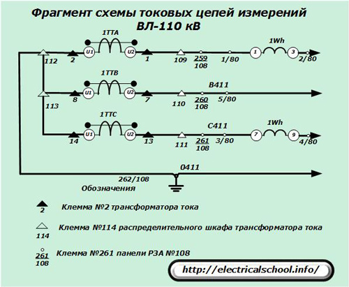
A similar arrangement of the control cables in the circuits that they connect between different objects of electrical equipment applies to the extended logic circuits of the electrical connections. The drawing shows a fragment of the operation of a similar part of the current circuits of the core for measuring HV 110 kV.
This shows:
-
black triangles — terminal installation of measuring transformers located at a height;
-
white triangles — terminals of an external distribution cabinet;
-
circles — terminals on the relay protection panel. In our case, it has a serial number — #108.
This diagram clearly shows that the control cable connects current circuits and assembles them directly from the windings of the measuring transformers to the relay protection and automation panels through an intermediate connection - a distribution terminal cabinet.
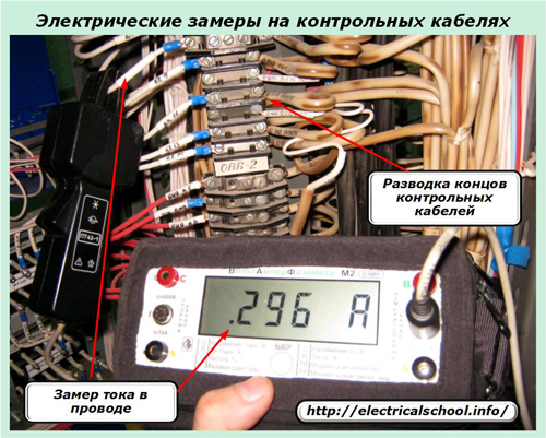
When installing the control cable, certain rules are followed for feeding wires to the terminal column and their marking, which is necessary for periodic preventive maintenance and for performing current control measurements of electrical signals during operation.
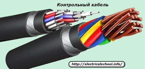
Control cable construction
The internal structure of each model is slightly different from all other products, as shown in the picture below for two different modifications.
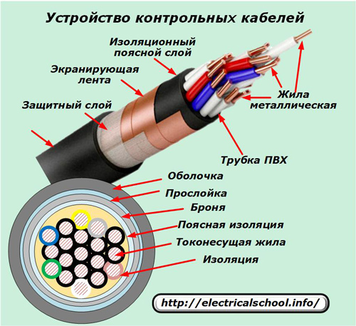
But they all have common elements:
-
conducting wires;
-
insulating layer on the core;
-
aggregate;
-
shell.
The control cable, depending on the requirements of the working conditions, can be supplemented with:
-
armor;
-
shielding tape.
Conductive core manufacturing features
It is an indispensable element of the cable and is made of metal:
-
aluminum;
-
aluminum copper composition;
-
or honey.
The conductor can be made from a single solid wire or from a large number of them by stretching to give flexibility to the overall structure. Single-core wires are used for cables operating in stationary conditions that are not subject to dynamic bending and torsional loads.
For the working conditions of the cable in mobile, mobile devices conductive cores are made of twisted wires. Copper core wires in them are covered with a layer of tin - they are tinned or remain clean, without a protective coating.
Inside the sheath of the control cable, a different number of cores can be used, ranging from four to 61. For aluminum, the cross-section of the wires should start from 2.5 mm square and more. But such products can be used exclusively in substations with a voltage of 110 kV or lower.
The secondary equipment of substations with a higher voltage of 220 kV and higher is allowed to be connected only with copper wires and cables. Low performance aluminum does not provide high reliability in critical equipment. Aluminum is banned in their secondary circuits.
The cross-section of the copper conductors of the control cables is standardized from 0.75 to 10 mm2. Thin diameters are used in low current communication circuits, telemechanics, telecontrol that do not create high signal powers.
For high-precision measurement systems that are sensitive to losses and voltage drops in the circuit, increased diameters of current conductors are used.
The metal of the conductive wires is necessarily covered with a dielectric layer, which excludes the occurrence of short-circuit currents and leaks between them. The marking is applied to the insulation layer:
1. the color of the shell;
2. or numbers.
In the first method, one color is used, or color stripes can be additionally created on it. Numerical marking is applied frequently, with a space between numbers of at least 3.5 cm.
The thickness of the insulating layer on the conductive core has an electrical strength that excludes the breakdown of the dielectric layer at the maximum operating voltage and directly depends on its cross section. It increases with increasing wire diameter.
The insulated wires are assembled into a common bundle and twisted to provide a standard number of twists that allow the cable to be bent in accordance with the data sheet.
Classification
Control cables differ in:
1. metal of the conductor;
2. metallic insulating material;
3. the shape of the wire;
4. shell material;
5. protective coating.
The dielectric layer on the base metal can be applied by:
-
rubber;
-
PVC compound;
-
self-extinguishing polyethylene;
-
low density polyethylene;
-
vulcanized polyethylene.
Wires are mainly made of round shape, but in some cases they have a flat shape.
The shell material can be:
-
rubber or non-flammable;
-
PVC compound.
The jacket for control cables working in extreme conditions is created by:
-
aluminum;
-
lead;
-
corrugated steel strip.
Shields and protective covers are designed for control cables operating in four classes of increased mechanical stress:
-
The first type of cable works indoors, in cable ducts and trenches, without being subjected to high tensile forces. Their armor is created by winding two strips of steel and coating them with an anti-corrosion compound.
-
The second type is intended for use in ducts, tunnels and rooms without tensile forces.
-
The third type is exploited in the ground, in trenches without significant tensile forces. They have an armor of double steel strips, protected by an outer cover - a PVC hose.
-
The fourth type is designed for laying in the ground and channels. They should not be subjected to high tensile strength. The armor consists of two steel wires covered with a layer of zinc and protected from above by a hose or a PVC-plastic cover.
Description of the mark
The cable is marked with the purpose of a concise designation to provide complete information about its composition and characteristics:
-
core and insulating layer materials;
-
the composition of the shell and its structure;
-
the presence of armor and its coating;
-
the number of conducting wires and their cross-section.
Symbols with capital letters are used to mark control cables:
-
the letter «K» stands for «control»;
-
the metal of the conductor is intended for: aluminum «A»; alumomed — «AM»; med — the absence of a letter;
-
wire insulation material: rubber — «P»; PVC compound — «B»; low-density polyethylene — «P»; self-extinguishing polyethylene — «Ps»;
-
sheath material: corrugated steel strip — «St»; tire — «R»; non-burning rubber — «H; PVC compound — «B»;
-
wire shape: flat — «P»; round — do not mark.
Operational characteristics
Effect of ambient temperature
When an electric current passes through a metal core heating is generated, which can affect the properties and structure of the insulation layer, deteriorate them or even create a breakdown of it. Therefore, the load passing through the cable is monitored by protective devices and limited to tripping by circuit breakers.
The operating temperature of the cable must correspond to the parameters specified in the technical conditions for its operation.
At low ambient temperatures, many types of insulation, especially those based on polyethylene, lose their plastic properties and flexibility. Even from a slight bending in the cold, they crack, become covered with a layer of cracks and lose their dielectric properties.
Therefore, at temperatures below -5 degrees Celsius, the installation and laying of control cables is prohibited, and in winter, preventive repair work on the street is not even planned.
If it is necessary to eliminate malfunctions that occurred in the control cables during freezing, then there is a special technology for their preparation and heating by connecting currents through the wires with control of their temperature.
Work in an aggressive environment
Chemical exposure to the control cable is limited by the use of a rubber sheath for its sheath, which is flexible and highly resistant to hygroscopicity. However, these things:
-
is more expensive;
-
more susceptible to heat and do not allow the temperature to rise above 65 degrees;
-
loses elasticity with prolonged use.
Exposure to light
Prolonged exposure to sunlight can destroy some types of cable sheaths. They are best protected from this effect with armor, lead, and aluminum. But modern casings made of rubber and plastics do not need a metal casing for this service life parameter declared by the manufacturer.
Mechanical tensile loads
They can be created when the installation technology is violated or during operation due to increased soil pressure for various reasons. To counteract these forces, the cable is placed in an armor made of metal strips.
Thus, the control cable:
-
it is used when it is necessary to transmit control or other signals between objects of the electrical circuit located at a distance;
-
created by different structures and classes of protection corresponding to certain working conditions.