Design and application of oil and gas filled high voltage cables
Underground high voltage cables have been used to transmit electricity for many years and a number of different technologies have been developed over the years.
Insulated gas and oil pipelines have technical, environmental and operational characteristics that make them a very good alternative when high voltage transmission is required in a limited space, for example when it is impossible to use overhead power lines.
High voltage cables in Spain for voltage 400 kV
Gas and oil insulated transmission cables (high pressure gas and oil cables) are a safe and flexible alternative to overhead lines and take up much less space while providing the same power transmission.
As they have little or no impact on the landscape and their minimal electromagnetic emissions mean they can be used close to or even in buildings, oil and gas filled high voltage cables can be considered for a wide range of applications .
The magnetic indication B that can be measured near such a structure is very low, much lower than for an equivalent overhead line. At a distance of 5 meters from the pipes it is less than 1 μT.
They are suitable for providing the continuation of underground overhead lines, connecting power stations to the power grid or as a compact way of connecting large industrial plants to the general grid.
When used in cables with increased pressure, the dielectric strength of the cable insulation is significantly increased, and its thickness and, accordingly, costs are reduced. The increased pressure in oil- or gas-filled cables is generated inside the insulation through a hollow core or other conduits along the cable and is applied outside the insulation if the cable is placed in a steel conduit.
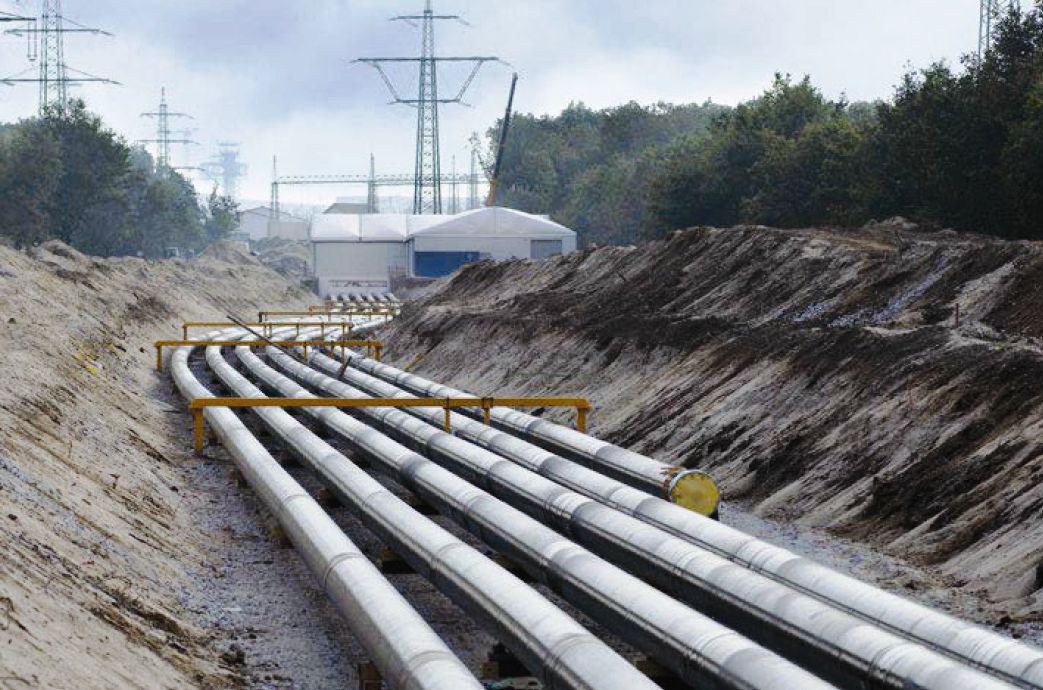
Construction of a cable line with high-voltage gas-filled cables
Gas-filled cables use water-implemented insulation with a depleted layer, in the layer of which there is an inert gas under pressure, which has good electrical characteristics and high thermal conductivity (nitrogen, SF6 gas, etc.). Replacing the air with nitrogen or SF6 gas avoids oxidation of the insulation.
According to the magnitude of the pressure, cables are distinguished with low (0.7 — 1.5 atm), medium (up to 3 atm) and high (12 — 15 atm) pressure. The first two types of cables are mainly made of three-phase for 10 — 35 kV, and the high-pressure cables — single-phase for 110 — 330 kV.
Single-core oil-filled cables for 110 kV are made with one oil-conducting channel in the center of the hollow core, and for voltage 500 kV - with a central channel in the core and channels under the protective sheath.
Three-phase oil-filled design
The increase in pressure requires strengthening the protective shell by applying reinforcing metal strips over it, which are protected from corrosion by suitable coatings, as well as an armor of galvanized steel wires.
A major disadvantage of the modern high voltage line made with oil-filled cable is the need for very expensive and complex auxiliary equipment, such as: supply tanks, pressure tanks, stop, couplers and end connectors.
Compensation of changes in the volumes of the impregnating composition is carried out using supply devices consisting of supply tanks and a pressure tank. The feed tanks ensure that a large amount of oil is fed into or out of the cable with little change in pressure, and the pressure tank maintains the pressure in the cable with any change in oil volume.
The oil moves along the cable along the central channel of the current-carrying wire. The cable line is divided by limiting bushings into separate make-up parts.
Oil-filled cable's strongest competitor is pressurized gas cable. Compared with oil-filled high voltage gas-filled cable, it requires lower line construction costs, does not need complex auxiliary equipment, and is very simple in both installation and operation.
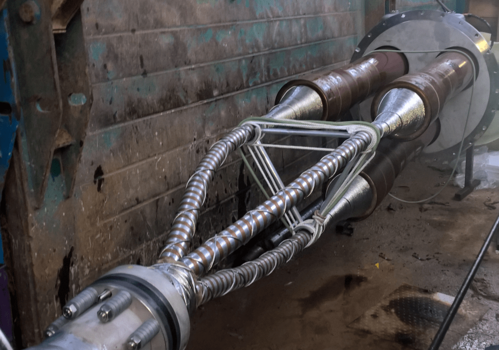
Installation of a three-phase line with gas-filled cables
The main advantage of gas-filled cables compared to oil-filled cables is the simplicity of supplying the cable line with gas, the possibility of laying the cable on steeply inclined and vertical routes.
Gas-filled cables are most widely used for voltage 10 — 35 kV.At voltages of 110 kV and higher, gas-filled cables, compared to oil-filled ones, have lower impulse strength and higher thermal resistance. Therefore, these cables are rarely used in our country at voltages of 110 kV and above.
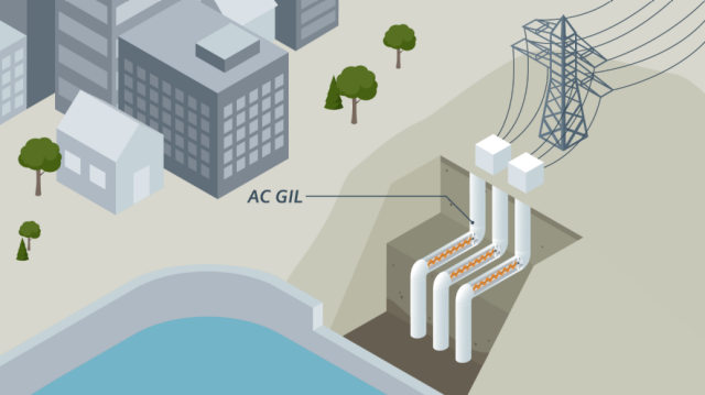
In European countries, on the contrary, oil-filled cables (Oil Filled Cable) are used less often than gas-filled cables (gas-insulated transmission lines, GIL).
This technology began to be applied in Europe approximately in the 70s. It is specially designed to provide the possibility of burying high voltage networks in an urban environment. Currently, there are many completed projects using gas-filled cables for voltages up to 500 kV.
The advantage of gas-filled cables is a relatively large margin of safety in the event of an emergency drop in pressure, which allows them not to be immediately disconnected when the pressure drops.
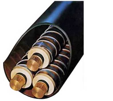
Gas-filled cable design
Cables in a steel pipeline under pressure oil are three single-core cables with paper insulation impregnated with mineral or synthetic oil (without lead sheath), which are located in a steel pipeline with pressure oil up to 15 atm.
Typically, more viscous oils are used to impregnate the insulation, and less viscous oils are used to fill the pipeline. Such cable lines in steel pipelines with pressurized oil are used for voltages of 110 — 220 kV.
The insulation is covered with a screen made of metallized paper or perforated copper strips, on which a sealing coating is applied - a polyethylene sheath that prevents moisture from entering the cable during transportation.
Two or three semi-circular bronze or copper wires are applied spirally on the sealing coating, which are designed to facilitate the pulling of the cable into the conduit, in addition, they keep the phases at a certain distance from each other, which improves the circulation of the oil and ensures electrical contact of the cable screens with the pipeline.
The steel tube, which maintains the pressure in the cable, is a reliable protection against mechanical damage. The oil pressure on the insulation is transferred through the polyethylene sheath.
Overhead to cable transition
The weak point of a high-voltage cable is usually the connectors. One of the main tasks in the development of high-voltage cable lines is the creation of a connector that is convenient for installation and has an electrical strength that is not less than that of the cable.
End connectors are installed at the ends of the cable line, and semi-stop connectors are installed every 1 — 1.5 km of the line (they prevent the free exchange of oil between adjacent sections of the pipeline).
The preset oil pressure in the pipeline is maintained by an automatically operating unit that supplies oil to the pipeline when the pressure drops and removes excess oil when the pressure rises.
In the connectors of oil-filled cables, the electrical connection of the current-carrying wires and the connection of the oil channels of the cable take place.
The cores are pressed together and the continuity of the oil channel is ensured by a hollow steel tube (welding or brazing is not allowed due to the presence of oil).
A ground shield (tinned copper braid) is applied along the entire length of the bushing, and the outside of the bushing is enclosed in a metal housing.
Cable bushing of oil filled high voltage cable
Cables in a pressurized gas steel pipeline differ from the previous design only in that instead of mineral or synthetic oil, the pipeline is filled with a compressed inert gas, usually nitrogen at a pressure of about 12-15 atm. The advantage of such cables is a significant simplification and cost reduction of the line supply system.
Cable insulation is exposed not only to continuous exposure to industrial frequency voltage, but also to impulse voltage, since the cables are connected directly to overhead lines or to electrical equipment of open substations and switchgears that perceive the effects atmospheric waves.
The impulse strength of an oil-filled cable is higher than that of a gas-filled cable, regardless of the oil or gas pressure values in them. For any type of cable, the impulse breakdown voltage can be increased by reducing the thickness of the paper strips, i.e. by reducing the gaps between them. Oil-filled cables or cables under external gas pressure, where the gaps in the insulation are filled with an impregnating compound, have the highest breakdown voltages.
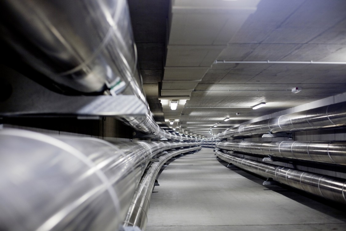
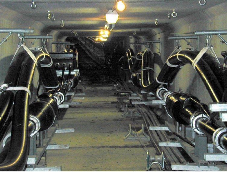
Gas-filled high-voltage cables in an underground manifold (tunnel) can easily be moved between cables, but this type of installation requires almost no maintenance
High-pressure gas and oil-insulated cable pipelines have already proven their technical reliability for several decades, as they provide exceptional safety in operation and even in the event of a breakdown, in addition to their very good transmission characteristics.
The condition of the insulation of the cable lines during operation is checked through preventive tests, which make it possible to identify gross violations of the integrity of the insulation and defects in it (phase grounding, wire breaks, etc.), as well as to measure the insulation resistance, leakage currents, dielectric loss angle, etc.
It should be noted that for the insulation of cable lines, preventive tests are the only method of detecting defective spots in the insulation, since the cable line is inaccessible for inspection and preventive repair. Therefore, preventive testing of the insulation of cable lines should quickly identify defects in the insulation of cables and therefore reduce the emergency of the network.
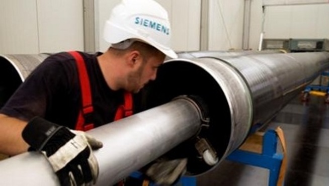
In addition to the article — Siemens is developing a gas transmission line
The new line is designed to transmit up to five gigawatts (GW) of power per system. Germany's Federal Ministry of Economic Affairs and Energy is granting 3.78 million euros for this development project.
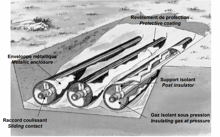
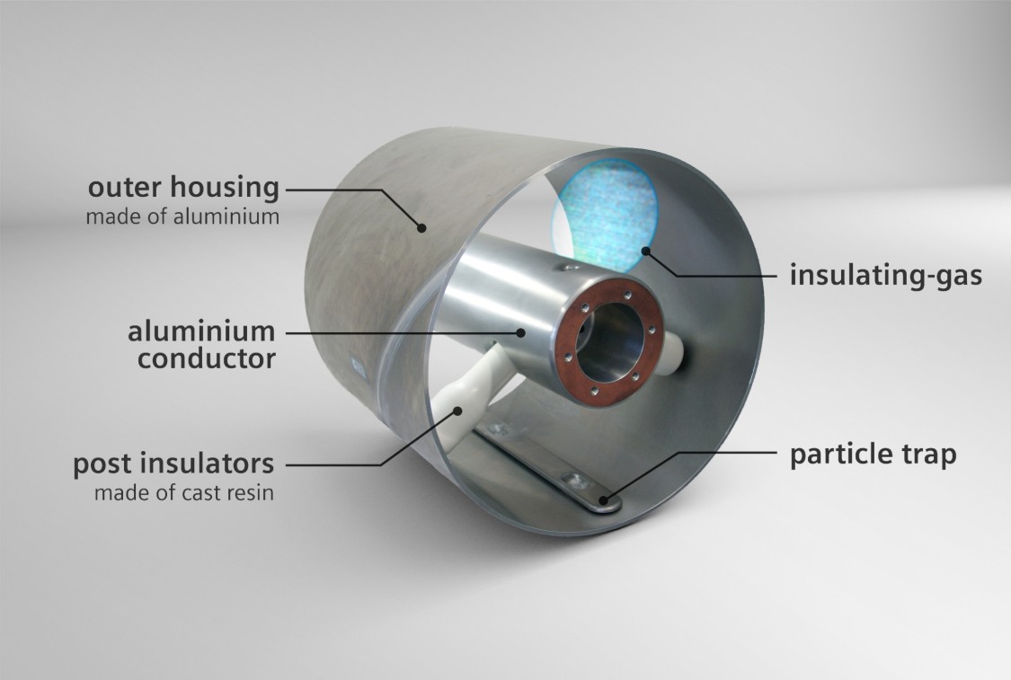
Direct current electrical wires will be based on the technology of the existing gas-insulated transmission line (TL), which consists of two concentric aluminum pipes. A mixture of gases is used as an insulating medium. Until now, gas-insulated cable lines were only available for alternating current.
Expansion of the transmission network is necessary if 80% of Germany's electricity demand is to be met by renewable energy sources by 2050.
Electricity generated wind turbines in the northern part of the country and along the coast of Germany, will have to be transported as efficiently as possible to the freight centers in the southern part of Germany.DC transmission is best suited for this because of its low electrical losses compared to AC transmission.
Network development using high voltage direct current (HVDC) using overhead transmission lines and gas-insulated direct current transmission lines laid underground in certain areas can be realized using significantly fewer resources than three-phase technology .
"Underground direct current transmission is essential for Germany's transition to a new electricity structure, as its development will initially take place in Germany. Later, inquiries from other EU countries or other countries around the world will be quite possible. In any case, with the development of a direct current gas transmission line, Germany will play a leading role in the design of future transmission systems," said Denis Imamovic, responsible for gas transmission systems at Siemens Energy Management.