Phase indicator - how it works and how to use it
There are situations when when connecting an electrical installation to a three-phase network it is important to observe the sequence of phases. The conclusion is that the direction of rotation of the rotor of an asynchronous three-phase motor connected, for example, to a three-phase network, cannot be accurately predicted without strict observance of the phasing.
And if we are talking, say, about the drive of the fan of the ventilation system or the drive of a powerful pump, then the direction of rotation is extremely critical here, and observing the correct phase sequence of the currents in the stator windings is simply necessary. In order for the connection to be correct, they use a special electrical measuring device - a phase indicator.
With correct phasing, the phases follow conventionally, starting with A, then B, then C, and so on in a circle. And the direction of rotation of the motor is determined exactly by this order.
For example, when you connect the supply wires in the order A, B, C to the corresponding terminals, the rotor rotates clockwise, but if two phases are reversed and the order turns out to be, say, A, C, B, then the rotor will rotate counterclockwise and the entire technological process can be disrupted and equipment that is sensitive to the direction of rotation of the drive will generally fail.
If the two wires are now swapped, the direction of rotation will again become correct, as the phase rotation order will change to the correct one.
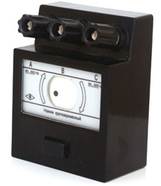
Phase indicators are of a different type. The most obvious option is an electromechanical one, such as the I517M, which itself is a small asynchronous three-phase electric motor sensitive to phase rotation.
The terminals of such a phase indicator are the terminals of the stator windings, therefore, the rotation of the indicator disk with a mark on it will unequivocally reflect the order of the phase sequence, it will show it in the direction of rotation of the disk. If the phases follow in the order A, B, C — the disc will rotate clockwise, if the order is broken (A, C, B) — counterclockwise.
The contrasting marking on the disk will make it easier to determine the direction of its rotation by eye. If at least one of the phases is missing, then the disk will not spin.

Another type of the simplest phase indicators is a phase indicator of incandescent lamps or neon lamps (or LEDs). The complex resistance of the circuits plays a crucial role here, since the signal lights are connected through capacitors.
If the first bulb is powered through a capacitor, it glows brighter, while the second bulb is powered through a resistor and glows dimmer or not at all.Knowing in which branch the capacitor is located and in which - the resistor, it is possible to determine the order of phase rotation.
This principle is the basis of phase indicator circuits based on neon lamps (and LEDs). There are also more complex electronic phase indicators, the principle of operation of which is based on a graphic analysis of phase voltages, but we will consider a simpler version with a visual diagram.
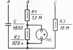
A simple phase indicator that anyone can assemble independently contains three asymmetric branches, each of which has its own components. Despite the simplicity of the circuit, it will allow you to determine the order of phase rotation in a three-phase network without the need to connect to a neutral wire.
The principle here is simple: an unbalanced load causes correspondingly unbalanced phase currents, and the voltage drop across the active and reactive components of the circuit will be different.
In one phase there is capacitive load, in the other two - active loads. When this circuit is connected to a three-phase network, provided that the nominal values are close to those indicated in the diagram, the phase voltages will be as follows: the B-branch will have a voltage of 1.49Uph, and in the C branch , the voltage will be 0.4Uph, where Uph is the usual phase voltage of a symmetrical three-phase network (220 volts, for example).
So, if the connection is correct and the phases follow in the order A, B, C, then in branch B the voltage will exceed three times the voltage of branch C and if the voltage of the resistor R2 is more than 60 volts, then the neon lamp HL will light up exactly , showing the correct phase.
If two phases are reversed, then the voltage drop across resistor R2 will not be enough to power the neon lamp and it will not light up, which will indicate incorrect phasing (incorrect phasing corresponds to the reverse rotation of the motor).
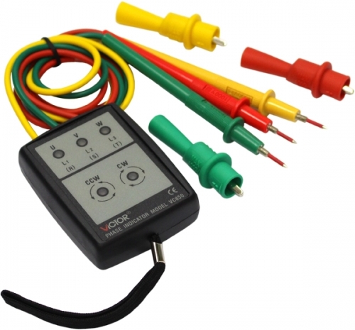
As a rule, the phase indicator contains, in addition to the box, three probes, each of which has a colored and sometimes letter marking of the phases: L1 — red, L2 — yellow, L3 — green or: green, red, yellow, — the order is exactly this .
The probes are simply mounted on the phase wires, then the button is pressed.
Some devices have a button (such as the electromechanical I517M), others do not, for example, the Victor VC850 does not have a button, it is enough to install the probes and the device will signal the correct phasing not only by the glow of the LEDs, but also by sound: intermittent for correct phase or continuous — for reversible.
Remember that mains voltage is life-threatening, so be careful when using the phase indicator!