Methods of controlling the heating of electrical equipment during operation
Four measurement methods are used to control the heating of electrical equipment: the thermometer method, the resistance method, the thermocouple method, and the infrared method.
Control of heating of electrical equipment by the thermometer method
The thermometer method is used to measure the temperature of accessible surfaces. They use mercury, alcohol and toluene glass thermometers immersed in special sleeves, hermetically built into covers and casings of the equipment.
Mercury thermometers have higher accuracy, but are not recommended for use in the presence of electromagnetic fields due to the large error caused by additional heating of mercury by eddy currents.
If it is necessary to transmit the measurement signal over a distance of several meters (for example, from the heat exchanger in the cover of the transformer to the level of 2 ... 3 m from the ground), use thermometers of the gauge type, for example thermal alarms TSM-10.
The thermal signaling device TCM-10 consists of a thermal cylinder and a hollow tube connecting the balloon to the spring of the indicating part of the device.
The thermal signal is filled with liquid methyl and its vapors. When the measured temperature changes, the vapor pressure of methyl chloride changes, which is transmitted to the pointer of the device. The advantage of manometric instruments lies in their vibration stability.
Control of heating of electrical equipment by the method of resistance
The resistance method is based on reading the change in the resistance value of a metal conductor with its temperature. For power transformers and synchronous compensators, they use thermometers with a gauge-type pointer... The wiring diagram of a remote electrothermometer is shown in the figure.
Depending on the temperature, the liquid fills the electrothermometer measuring rod, acting through a connecting capillary tube and a system of levers on the pointer arrow.
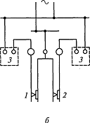 Remote manometric type electrothermometer: 1 and 2 — signal contacts; 3 — relay
In a remote electrothermometer, the pointer arrows have contacts 1 and 2 to signal the temperature set by the setting. When the contacts are closed, the corresponding relay 3 in the alarm circuit is activated.
To measure the temperature at individual points of synchronous compensators (in the steel measuring channels, between the rods of the windings for measuring the temperature of the windings and other points) thermistors... The resistance of the resistors depends on the heating temperature at the measuring points.
Thermistors are made of platinum or copper wire, their resistances are calibrated at certain temperatures (at a temperature of 0 ° C for platinum, the resistance is 46 Ohm, for copper — 53 Ohm; at a temperature of 100 ° C for platinum — 64 Ohm, for copper — respectively 75.5 ohms).
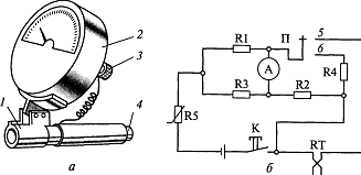
 A circuit for measuring temperature using a thermistor
Such a thermistor R4 is included in the arm of the bridge assembled from resistors. A power source is connected to one of the diagonals of the bridge and a measuring device is connected to the other. Resistors R1 … R4 in the arms of the bridge are chosen in such a way that at the nominal temperature the bridge is in equilibrium and there is no current in the circuit of the device.
If the temperature deviates in any direction from the nominal, the resistance of the thermistor R4 changes, the balance of the bridge is disturbed, and the arrow of the device deviates, indicating the temperature of the measured point. A portable device is based on the same principle. Before the measurement, the pointer of the device must be in the zero position.
To do this, the K button supplies power, the P switch is set to position 5, and the device needle is set to zero with a variable resistor R5. Switch P is then moved to position 6 (measurement). The contact temperature is measured by touching the sensor head to the contact surface and pressing the rod on the head of the electrothermometer (when pressed, the button K closes and power is applied to the circuit). After 20 ... 30 s, the measured value of the contact temperature is read from the scale of the device.
Using resistance thermometers to measure the temperature of heating electrical equipment
The means for remote measurement of the temperature of the winding and the steel of the stator of the generators, synchronous compensators, the temperature of the cooling air, hydrogen are resistance thermometers, in which the dependence of the resistance value of the conductor on temperature is also used.
Resistance thermometers are varied. In most cases, this is a thin copper wire wound bifilarly on a flat insulating frame, with an input resistance of 53 Ohm at a temperature of 0 ° C. As a measuring part, working together with resistance thermometers, automatic electronic bridges and logometers equipped with a temperature scale are used .
The installation of resistance thermometers in the stator of the machine is carried out during its manufacture in the factory. Copper resistance thermometers are placed between the winding bars and at the bottom of the groove.
 Control of heating of electrical equipment by the thermocouple method
The thermocouple method is based on the use of the thermoelectric effect, i.e. the dependence of the EMF in the circuit on the temperature of the connection points of two different conductors, for example: copper - constantan, chromel - copper, etc.
If the measured temperature does not exceed 100 ... 120 ° C, then there is a proportional relationship between the thermoEMF and the temperature difference between the heated and cold ends of the thermocouple.
Thermocouples are connected to compensation type meters, DC potentiometers and automatic potentiometers that are pre-calibrated.Thermocouples are used to measure the temperatures of the structural elements of the turbine generators, the cooling gas, the active parts, for example the active steel of the stator.
Control of the heating of electrical equipment by the method of infrared radiation
In the last decade, the approach to the methods of diagnosing electrical equipment and assessing its condition has changed significantly. Along with traditional diagnostic methods, modern highly effective control methods are used, which ensure detection of electrical equipment defects at an early stage of their development. The field of control of oil-filled equipment under operating voltage has expanded significantly, methods and rejection standards have been developed to assess the condition of equipment by the composition of gases dissolved in oil, a thorough analysis of transformer oil is carried out, which makes it possible to assess the condition of the paper insulation of the windings of power transformers, the thermographic examination of electrical installations became widespread, etc.
The infrared radiation method is the basis of devices that work by fixing infrared radiation emitted by heated surfaces. In the energy sector, they are used as thermal imagers (thermoimagers) and radiation pyrometers... Thermal imagers provide an opportunity to obtain a picture of the thermal field of the object under study and its temperature analysis. With the help of a radiation pyrometer, only the temperature of the observed object is determined.
Very often a thermal imager is used together with a pyrometer.First, objects with increased heating are detected using a thermal imager, and then its temperature is determined using a pyrometer. Therefore, the accuracy of the temperature measurement is primarily determined by the parameters of the pyrometer used.
The production of pyrometers of various designs and purposes has been mastered by many enterprises in Russia. In terms of technical parameters, domestic pyrometers are not inferior to the best foreign samples. The choice of the type of pyrometer when purchasing depends primarily on the possible area of its application and related factors. Infrared diagnostics should be carried out with devices that provide sufficient efficiency in determining a defect in operating equipment.