How the megohmmeter works and works
To measure the insulation resistance in electrical engineering, a special electrical measuring device «megohmmeter» is used. Unlike a conventional ohmmeter, a megohmmeter is designed to measure high resistance — from hundreds of kilohms to tens of megohms. Therefore, in the process of working with this device, the voltage of its probes can vary from 100 volts to 2500 volts.
The megohmmeter is connected to the circuit in parallel with the section whose resistance you want to know, usually this section is the space between two wires isolated from each other by a layer of insulation. The probes are connected to their own wire: the first («Z») and second probe («L») of the device are connected between the ground (and the first wire) and the second wire, and the third probe (» E «), if there is one, is connected, if necessary, to a cable screen.
The principle of operation of a megohmmeter is very similar to the principle of operation of an ammeter, taking into account the known dependence of the current value on voltage and resistance (Ohm's Law). Megometers, respectively, like ammeters, are analog and digital.
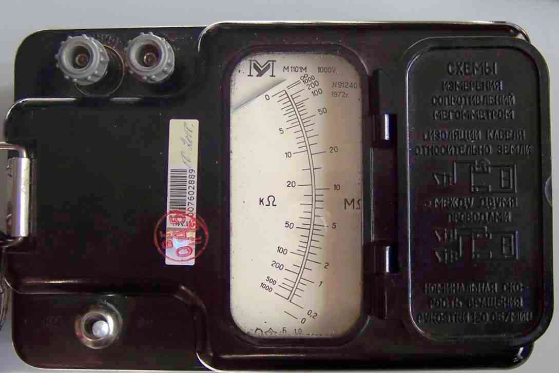
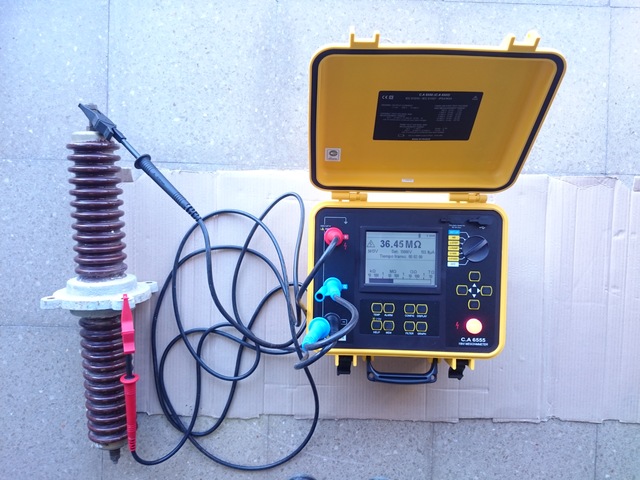
In analog instruments, readings are indicated by an arrow on a scale calibrated in megohms. In digital megohmmeters — in the form of the same numbers, only on the display. Devices of both types allow you to diagnose wiring, check the state of insulation of windings of transformers and electric motors, test various electrical insulation materials, perform service maintenance of various electrical machines and installations, etc.
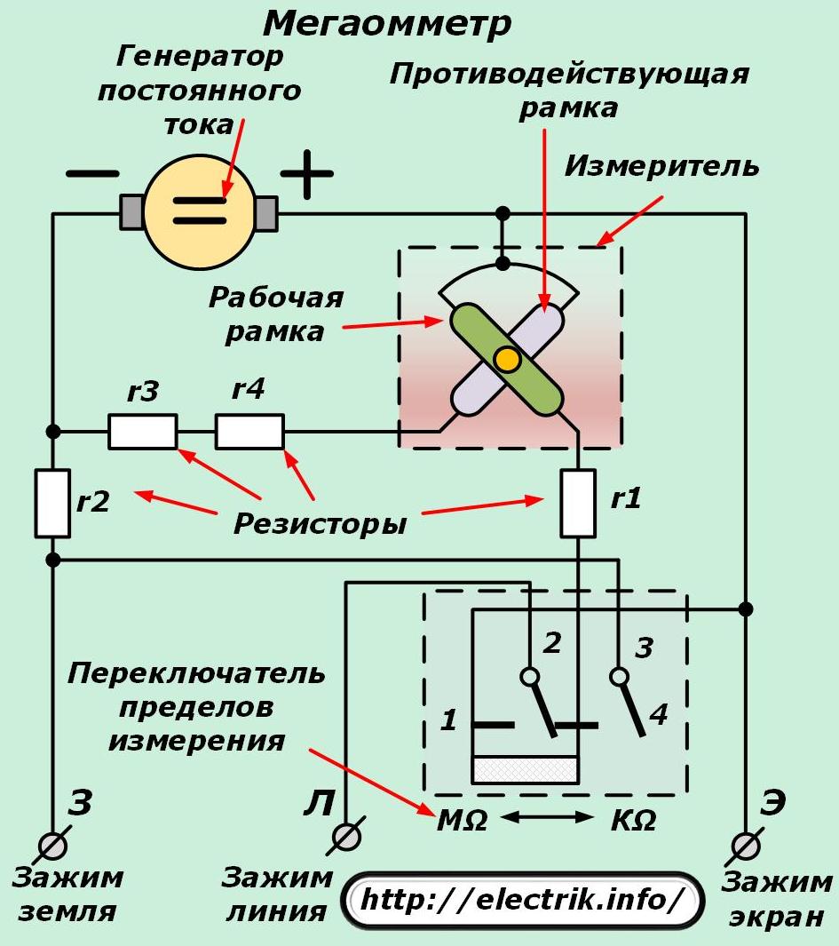
An analog megohmmeter refers to devices of a magneto-electric system where the current passing through the measured resistance is essentially measured and practically compared to the current through the internal circuit of the device (if the system is two coils).
The mutual deviation of the coils through which the reference and measured current flow inside the device, or the deviation of the coil with the measured current in the magnetic field of a permanent magnet, leads to a deviation of the device arrow connected to the coil, indicating resistance, since according to the law of Ohm it is inversely proportional to the current.
Since the voltage is known, by measuring the current through the circuit it is easy to immediately calculate its resistance and display the result on a scale. There are analog megometers powered by a built-in dynamo—you turn the knob—the device operates as long as the required voltage is applied to its probes.

A digital device works a little differently. There are no physical bias coils here, but there is a source of precisely calibrated DC voltage which is connected in series with the circuit through the digital ammeter circuit whose resistance is to be found.Depending on the characteristics of the investigated circuit, the voltage of the probes of the device will be different, ranging from 100 volts, ending with all 2500 volts, if the resistance of a high voltage circuit is measured.
This voltage is selected by a special switch or buttons on the dashboard. Of course, there are standards that circuits with different operating voltages are checked by the corresponding voltage on the megohmmeter probes. Digital megohmmeters can be powered by batteries, accumulators, individual power supplies.
When measuring resistance with a megohmmeter, the following standards are based:
-
Electrical circuits with an operating voltage of up to 50 volts are tested with a 100-volt megohmmeter until the circuit resistance is not less than 0.5 megohms. Semiconductor devices included in the diagnostic circuit must be shunted to prevent damage.
-
Electrical circuits with an operating voltage of 50 to 100 volts are tested with a 250-volt megohmmeter.
-
Electric circuits with an operating voltage of 100 to 380 volts are tested with a megohmmeter voltage of 500 to 1000 volts. As for the lighting, it is tested with a voltage of 1000 volts, while the resistance should not be less than 0.5 megohm.
-
Electric circuits with an operating voltage of 380 to 1000 volts are tested with a megohmmeter voltage of 1000 to 2500 volts. This type of equipment includes switchgear, switchboards and wires. The resistance of the circuit section (each section is measured separately) should not be less than 1 megohm.
Only trained personnel with an electrical safety approval group of at least third are allowed to work with a megohmmeter in enterprises, since during the operation of the device, high voltage is present on its probes, which is dangerous for the human body. Instrument probes therefore have insulated handles with support lugs. But even despite the insulated handles, work with the megohmmeter is always done in protective rubber gloves.

How to make measurements with a megohmmeter
Starting to make measurements, the first step is to check the device by closing your probes against each other - a working device will show zero, then open - the megohmmeter should show infinity.
Before working directly with the circuit, first always check that there are no people nearby who could accidentally touch the circuit under test during the measurement.
From the wires to which the megohmmeter should be connected, the operating voltage is first removed, that is, the circuit is de-aired.
Then briefly connect each of its parts to the ground electrode — to neutralize the residual static charge on the wires.
One of the wires is grounded, the "Z" probe of the megohmmeter is connected to it, then the second probe is connected to the second (ungrounded) terminal of the circuit under test. Take readings.
After - turn off the device, briefly ground the previously ungrounded terminal of the circuit under investigation to neutralize the residual static charge on it. The conclusions of the megohmmeter are discharged in the same way. The ground (and portable ground electrode) can then be removed.
See also on this topic:How is the cable insulation test performed?