How laser meters work
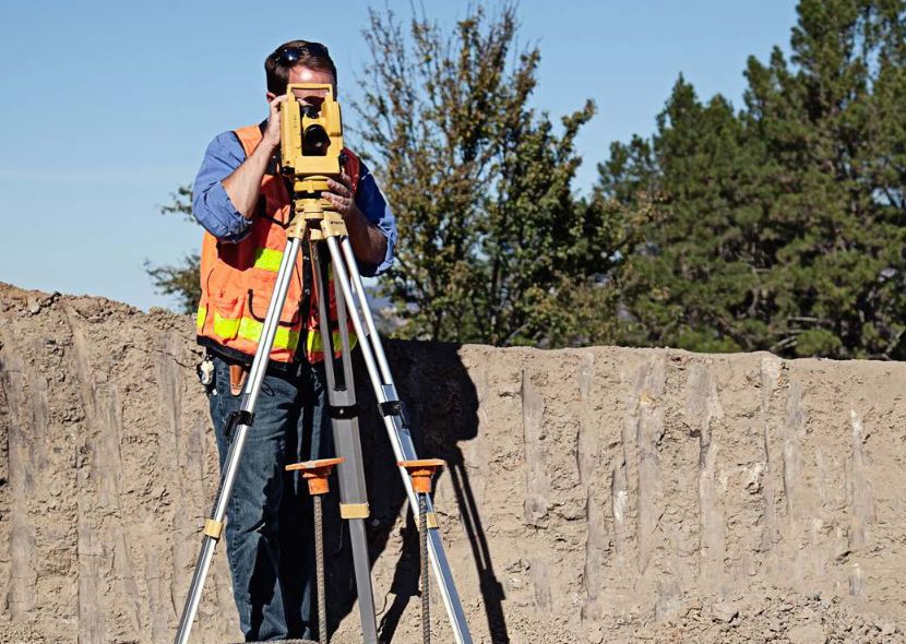
Construction and related engineering surveys are not complete without engineering-geodesic works. This is where laser measuring devices prove to be particularly useful, allowing you to more effectively solve the relevant problems. Processes that are traditionally carried out using classic levels, theodolites, linear measuring devices can now show higher accuracy and can usually be automated.
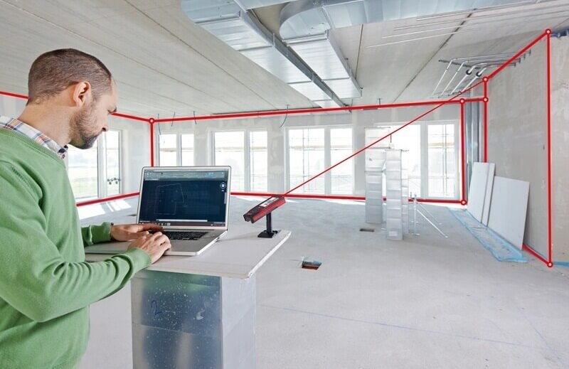
Geodetic measurement methods have developed significantly with the advent of laser surveying instruments. Laser beam it is literally visible, unlike the target axis of the device, which facilitates planning during construction, measurement and monitoring of results. The beam is oriented in a certain way and serves as a reference line, or a plane is created, in relation to which additional measurements can be made using special photoelectric indicators or by visual indication of the beam.
Laser measuring devices are being created and improved all over the world.Mass-produced laser levels, theodolites, attachments for them, plumb bobs, optical rangefinders, tacheometers, control systems for construction mechanisms, etc.
So, compact lasers are placed in a shock-proof and moisture-proof system of the measuring device, while demonstrating high reliability of operation and stability of the beam direction. Usually, the laser in such a device is installed parallel to its aiming axis, but in some cases the laser is installed in the device, so the direction of the axis is set using additional optical elements. The sight tube is used to direct the beam.
To reduce laser beam divergence, a telescopic system, which reduces the angle of divergence of the beam in proportion to its increase.
The telescopic system also helps form a focused laser beam hundreds of meters away from the instrument. If the magnification of the telescopic system is, say, thirty times, then a laser beam with a diameter of 5 cm at a distance of 500 m will be obtained.
If done visual indication of the beam, then a screen with a grid of squares or concentric circles and a leveling rod are used for readings. In this case, the reading accuracy depends both on the diameter of the light spot and on the amplitude of the beam oscillation due to the variable index of refraction of air.
Reading accuracy can be increased by placing zone plates in the telescopic system—transparent plates with alternating (transparent and opaque) concentric rings attached to them. The phenomenon of diffraction splits the beam into bright and dark rings. Now the position of the axis of the beam can be determined with high accuracy.
When using photoelectric indication, use different types of photodetector systems. The simplest thing is to move a photocell along a vertically or horizontally mounted rail across the light spot while simultaneously recording the output signal. The error in this method of indication reaches 2 mm per 100 m.
More advanced are the double photodetectors, for example, of split photodiodes, which automatically track the center of the light beam and register its position at the moment when the illumination of both parts of the receiver is identical. Here the error at 100 m reaches only 0.5 mm.
Four photocells fix the position of the beam along two axes, and then the maximum error at 100 m is only 0.1 mm. The most modern photodetectors can also display information in digital form for convenience in processing the received data.
Most laser rangefinders produced by modern industry are pulsed. The distance is determined based on the time it takes for the laser pulse to reach the target and back. And since the speed of the electromagnetic wave in the measuring medium is known, then twice the distance to the target is equal to the product of this speed and the measured time.
The sources of laser radiation in such devices for measuring distances over a kilometer are powerful solid state lasers… Semiconductor lasers are installed in devices to measure distances from several meters to several kilometers. The range of such devices reaches 30 kilometers with an error within fractions of a meter.
A more accurate range measurement is achieved by using the phase measurement method, which also takes into account the phase difference between the reference signal and the one that has traveled the measured distance, taking into account the modulation frequency of the carrier. These are the so-called phase laser rangefindersoperating at frequencies of the order of 750 MHz where gallium arsenide laser.
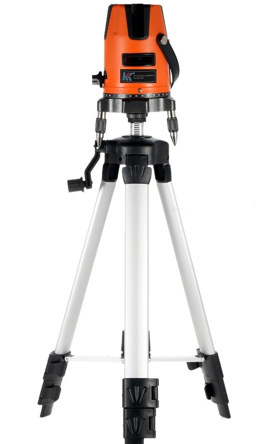
High-precision laser levels are used, for example, in the design of runways. They create a light plane by rotating the laser beam. The plane is focused horizontally due to two mutually perpendicular planes. The sensitive element moves along the staff, and the reading is carried out at half the sum of the boundaries of the area in which the receiving device generates a sound signal. The working range of such levels reaches 1000 m with an error of up to 5 mm.
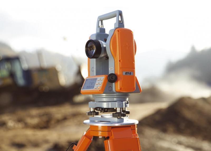
In laser theodolites, the axis of the laser beam creates the visible axis of observation. It can be directed directly along the optical axis of the device's telescope or parallel to it. Some laser attachments allow you to use the theodolite telescope itself as a collimating unit (to create parallel beams—laser and tube sight axis) and count against the theodolite's own reading device.
One of the first nozzles produced for the OT-02 theodolite was the LNOT-02 nozzle with a helium-neon gas laser with an output power of 2 mW and a divergence angle of about 12 arc minutes.
The laser with the optical system was fixed parallel to the theodolite telescope so that the distance between the beam axis and the theodolite aiming axis was 10 cm.
The center of the theodolite grid line is aligned with the center of the light beam at the required distance.On the objective of the collimating system there was a cylindrical lens that expanded the beam and a sector with an opening angle of up to 40 arc minutes for simultaneous work at points located at different heights within the available arrangement of the device.
See also: How laser thermometers work and work